Programming 3D games on Android with Irrlicht and Bullet (Part 1)
Posted on May 19, 2011, 11:00 pm, by xp, under Programming.
Just got a new Android phone (a Samsung Vibrant) a month ago, so after flashing a new ROM and installing a bunch of applications, what would I want to do with the new phone? Well, I’d like to know if the phone is fast enough to play 3D games. From the hardware configuration point of view, it is better equipped than my desktop computer in the 1990s, and since my desktop computer at the time had no problem with 3D games, I would expect it to be fast enough to do the same.
At first, I was considering downloading a 3D game from the market, but 3D games for Android are still rare, then why don’t I just create a 3D demo game myself?
After looking around which 3D game engines are available for the Android platform, I just settled down with Irrlicht. This is an open source C++ graphic engine, and not really a game engine per se, but it should have enough features to create my demo 3D application. And I like to have realistic physics in my game, so what could be better than the Bullet Physics library? This is the best known open source physics library, also developed in C++. The two libraries together would be an interesting combination.
Although Irrlicht was developed for desktop computers, but luckily enough, someone has already ported Irrlicht to the Android platform, which requires a special device driver for the graphic engine. And guess what? Someone has also created a Bullet wrapper for the Irrlicht engine. All of them in C++, and open source. All we need to do now to pull all these codes together to build a shared library for Android.
In this part, I’ll just describe what needs to compile all the codes for Android. Since we will compile C/C++ codes, you’ll need to download the Android native development kit. Please refer to the documentation on how to install.
We create an Android project, and add a jni folder. Then we put all the C/C++ source codes under the jni folder. I created three sub-folders:
- Bullet: All the Bullet Physics source codes. Actually, we only need the Collision, Dynamics, Soft Body and Linear Math libraries.
- Irrlicht: The Irrlicht 3D graphic engine source codes. This is the Android port of the engine.
- irrBullet: This is the Bullet wrapper for Irrlicht engine, which makes it easier to write your programs.
After, all we need to do is to create an Android.mk file, which is quite simple, really. You can read the makefile to see how it is structured. Basically, we just tell the Android NDK build tools that we want to build all the source codes for the Arm platform, and we want to link with the OpenGL ES library, to create a shared library called libirrlichtbullet.so. That’s about it.
However, there’s one minor thing to note though. Android does not really support C++ standard template library, but the irrBullet library made use of it. Therefore, in the jni folder, we need to add an Application.mk file, which contains the following line:
APP_STL := stlport_static
And that’s it. Now, you can run ndk-build to build the shared library. If you have a slow computer, it would take a while. If everything is alright, you should have a shared library in the folder libs/armeabi/. That shared library contains the Bullet Physics, Irrlicht and the irrBullet wrapper libraries. You can now create your 3D games for Android with it. In the next part, we will write a small demo program using this library.
You can download all the source codes and pre-built library here.
Programming 3D games on Android with Irrlicht and Bullet (Part 2)
Posted on May 20, 2011, 11:30 am, by xp, under Programming.
In the last post, we have built the Bullet Physics, Irrlicht and irrBullet libraries together to create a shared library for the Android platform. In this post, we are going to create a small demo 3D game for Android, using the libraries that we have built earlier.
This demo is not really anything new, I am going to just convert an Irrlicht example to run on Android. In this simple game, we are going to stack up a bunch of crates, and then we will shoot a sphere or a cube, from a distance, to topple the crates. The Irrlicht engine will handle all the 3D graphics, and the Bullet Physics library will take care of rigid body collision detection and all realistic physical kinetics. For example, when we shoot a sphere from the distance, how the sphere follows a curve line when flying over the air, how far it will fly, where it is going to fall on to the ground, how it reacts when it hits the ground, how it reacts when it hits the crates, and how the crates will react when being hit, etc, all these will be taken care of by Bullet Physics, and Irrlicht will render the game world accordingly.
Since it is easier to create Android project in Eclipse, we are going to work with Eclipse here. You will need to following tools to work with:
- Android SDK
- Android NDK
- Eclipse IDE
- Eclipse plugin for Android development.
I’m assuming you have all these tools installed and configured correctly. And I’m assuming you have basic knowledge on Android programming too, so I won’t get into the basic details here.
Let’s create a project called ca.renzhi.bullet, with an Activity called BulletActivity. The onCreate() method will look something like this:
-
-
@Override
-
public void onCreate(Bundle savedInstanceState) {
-
super.onCreate(savedInstanceState);
-
// Lock screen to landscape mode.
-
this.setRequestedOrientation(ActivityInfo.SCREEN_ORIENTATION_LANDSCAPE);
-
-
mGLView = new GLSurfaceView(getApplication());
-
renderer = new BulletRenderer(this);
-
mGLView.setRenderer(renderer);
-
-
DisplayMetrics displayMetrics = getResources().getDisplayMetrics();
-
width = displayMetrics.widthPixels;
-
height = displayMetrics.heightPixels;
-
-
setContentView(mGLView);
-
}
This just tells Android that we want an OpenGL surface view. We will create a Renderer class for this, something very simple like the following:
-
public class BulletRenderer implements Renderer
-
{
-
BulletActivity activity;
-
-
public BulletRenderer(BulletActivity activity)
-
{
-
this.activity = activity;
-
}
-
-
public void onDrawFrame(GL10 arg0)
-
{
-
activity.drawIteration();
-
}
-
-
public void onSurfaceChanged(GL10 gl, int width, int height)
-
{
-
activity.nativeResize(width, height);
-
}
-
-
public void onSurfaceCreated(GL10 gl, EGLConfig config)
-
{
-
activity.nativeInitGL(activity.width, activity.height);
-
}
-
}
The renderer class’s method will be invoked every time a frame needs to be rendered. There’s nothing special here. When the methods are invoked, we just invoke the native methods in the activity class, which will then call the C native functions through JNI. Since Irrlicht and Bullet are C++ libraries, we will have to write the main part of the game in C/C++. We keep very little logic in Java code.
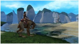
When the surface is first created, the onSurfaceCreated() method is invoked, and here, we just call nativeInitGL(), which will initialize our game world in Irrlicht. This will initialize the device, the scene manager, create a physical world to manage the rigid bodies and their collision, create a ground floor, and put a stack of crates in the middle point. Then, we create a first-person-shooter (FPS) camera to look at the stack of crates. The player will look at this game world through the FPS camera.
I’m not going to describe the codes line by line, since you can download the codes to play with it. But when you create the Irrlicht device with the following line of code:
-
device = createDevice( video::EDT_OGLES1, dimension2d(gWindowWidth, gWindowHeight), 16, false, false, false, 0);
Make sure you select the correct version of OpenGL ES library on your Android device. I have version 1.x on mine. But if you have version 2.x, change to video::EDT_OGLES2 instead.
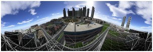
After the initialization, we would have a scene that looks like this:

When a frame is changed and needs to render, the onDrawFrame() method of the renderer is invoked. And here, we just call the nativeDrawIteration() function and will handle the game logic in C/C++ codes. The code looks like this:
-
void Java_ca_renzhi_bullet_BulletActivity_nativeDrawIteration(
-
JNIEnv* env,
-
jobject thiz,
-
jint direction,
-
jfloat markX, jfloat markY)
-
{
-
deltaTime = device->getTimer()->getTime() – timeStamp;
-
timeStamp = device->getTimer()->getTime();
-
-
device->run();
-
-
// Step the simulation
-
world->stepSimulation(deltaTime * 0.001f, 120);
-
-
if ((direction != -1) || (markX != -1) || (markY != -1))
-
handleUserInput(direction, markX, markY);
-
-
driver->beginScene(true, true, SColor(0, 200, 200, 200));
-
smgr->drawAll();
-
guienv->drawAll();
-
driver->endScene();
-
}
As you can see, this is very standard Irrlicht game loop, the only thing added here is a function to handle user input.
User input includes moving left and right, forward and backward, shooting sphere and cube. Irrlicht engine depends on keyboard and mouse for user interaction, which are not available on Android devices. So, we will create a very basic kludge to allow users to move around and shoot. We will use touch and tap to handle user input. Users will move their finger left and right, on the left part of the screen, to move left and right in the game world. Users will move their finger up and down, on the right part of screen, to move forward and backward in the game world. And tap on the screen to shoot. Therefore, the movement direction is translated into a parameter, called direction, and passed to the native code to be handled. We also grab the X and Y coordinates of the shooting mark, and pass them as parameters to native codes as well.
That’s it. You can now build it, package into an apk, install it on your Android device, and play with it. When you shoot on the stack of crates, you would have a scene that looks like this:

The performance on my Samsung Vibrant is ok, I get about 56 or 57 FPS, which is quite smooth. But if there are too many objects to animate, especially after we have shot many spheres and cubes, we will have a screen that hangs and jumps a bit, or sometimes, it stops to react to user input for a fraction of second. In a real game, we might want to remove objects that have done their work, so that the number of objects to animate is significantly reduced to maintain an acceptable performance.
The other important thing that we want to improve is user interaction and control. The Irrlicht engine is developed for desktop computers, it relies mainly on keyboard and mouse for user interaction. These are not available on mobile devices. The current demo attempted to use touch and tap on screen as user control, but it does not work very well. In a next post, we will try to create virtual controls on screen (e.g. buttons, dials, etc), and we might want to take advantage of the sensor as well, which is a standard feature on mobile devices now.
You can download the source codes of the demo here.
Programming 3D games on Android with Irrlicht and Bullet (Part 3)
Posted on May 23, 2011, 6:25 pm, by xp, under Programming.
In the last post, we have created a basic 3D demo application with Irrlicht, in which we put a stack of crates, and we topple them by shooting a cube or a sphere.
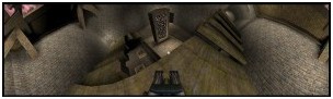
In this post, we will try to create an on-screen control so that you can move around with it, like using a hardware control. What we want to have is something like this, in the following screenshot:

What we have here is a control knob, sitting on a base. The knob is in the centre of the base. The on-screen control always stays on top of the game scene, and the position should stay still regardless of how you move the camera. However, users can press on the knob, and drag it left and right, and this, in turn, moves the camera left and right accordingly.
Obviously, you can implement movement direction along more than one axis too. And you can also have more than one on-screen control if you want, since it is a device with multi-touch screen. But that’s left to you as an exercise.
Placing an on-screen control is actually quite easy. All you have to do is to load a picture as texture, then draw it as 2D image on the screen, at the location you want to put the control. But since we want the on-screen control to be always on top, we have to draw the 2D image after the game scene (and all the scene objects) are drawn. If we draw the 2D image first, it will hidden by the game scene. There, in your loop, you would have something like this:
-
driver->beginScene(true, true, SColor(0, 200, 200, 200));
-
smgr->drawAll();
-
guienv->drawAll();
-
// Draw the on-screen control now
-
onScreenControl->draw(driver);
-
driver->endScene();
That’s the basic idea. Here, we have created an OnScreenControl class, which encloses two objects, one of VirtualControlBase class and the other, of VirtualControlKnob class. The draw() method of the OnScreenControl class looks like this:
-
void OnScreenControl::draw(IVideoDriver* driver)
-
{
-
base->draw(driver);
-
knob->draw(driver);
-
}
It just relegates the drawing works to its sub-objects, the control base and the control knob. Note that the knob has to be drawn after the base, otherwise, it will be hidden behind the base, instead of sitting on top of it. The draw() method of the base looks like:
-
void VirtualControlBase::draw(IVideoDriver* driver)
-
{
-
driver->draw2DImage(_texture,
-
position2d(pos_x, pos_y),
-
rect(0, 0, width, height),
-
0,
-
SColor(255,255,255,255),
-
true);
-
}
As you see, it just draws a 2D image with the texture, at the location specified. That’s it.
After putting the on-screen control in place, we have to handle user touch events on the screen. If users press on the knob (i.e. pressing within the square boundary of the knob image), and move the finger around, we update the position of the knob according to the movement direction. Here, we want to make sure that users can not drag the knob out of the control base boundary (or too far out of the boundary anyway), to make it look and behave like a real control. As users move the knob around, you want to update your camera’s position accordingly. And when the knob is released, you want to reset its position back to the centre of the control base.
That’s basically the idea. You can grab the source code here. Ugly codes, I warn you.
The major problem of programming Irrlicht on Android is the separation of Java codes and the C/C++ codes. If you want to limit your program to only Android 2.3 or later, you can probably write the whole program in C/C++, using the native activity class. That way, you don’t have to move back and forth between Java and C++. But if you want to run your program on older versions of Android, your Activity must be written in Java, and the main game logic written in C/C++. You then have to catch user interaction events in your Java code, pass them through JNI to your C/C++ code. There will be loss of information as you move back and forth, not to mention that there will be quite a bit of code duplication. You can certainly create a full wrapper for the Irrlicht and Bullet libraries, but that will be taxing your mobile device heavily, and will certainly have a negative impact on performance. And creating a full wrapper for these two libraries would be a heck of a job.
The other problem is that, Irrlicht is an engine developed for the desktop, where keyboard and mouse are the main input devices. The Irrlicht port to Android mainly concerns with a display driver for Android, but the port has not really gone deep into this area of user interaction. Therefore, as you write your Irrlicht-based Android program, you would have to hack together user input handling model, event model, etc. In my demo, I haven’t even touched that, I have just kludged together some primitive event handling codes. In order to have our program fit in those multi-touch based devices, we would have to dig into the Irrlicht scene node animator and event handling mechanisms, and work it out from there. For example, we will have to define our own scene node animator which would be based on touch events instead of keyboard and mouse events, and add it to the scene node that we want to animate. This is something that we are going to look into in our future posts.
原文地址:http://castano.ludicon.com/blog/2009/01/10/10-fun-things-to-do-with-tessellation/
Hardware tessellation is probably the most notable feature of Direct3D11.
Direct3D11 was announced at the last Gamefest and a technical preview was released in theNovember 2008 DirectX SDK. Hardware implementations are expected to be available this year.
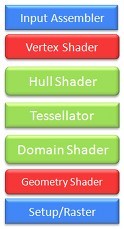
Direct3D11 extends the Direct3D10 pipeline with three new stages: Two programmable shader stages (the Hull and Domain Shaders), and a fixed function stage (the Tessellator). More details can be foundhere and here.
Rendering of Catmull-Clark subdivision surfaces is often mentioned as the primary application for the tessellation pipeline, but there are many other interesting uses that have not received that much attention.
I thought it would be interesting to take a closer look at those other applications, and submitted a proposal to do that at GDC’09. However, it seems that the organizers do not think tessellation is as interesting as I do, or they didn’t like my proposal, or maybe it’s just that they know I’m a lousy speaker. I will never know, because the gracious feedback of the GDC review committee can be represented by a single boolean.
In any case, here’s a brief overview of the 10 fun things that I was planning to talk about. I don’t get very deep into the technical details, but in future posts I may describe some of these applications more thoroughly. Please, leave your comments if there’s something you would like to learn more about.
PN-TRIANGLES
Curved PN Triangles is a triangle interpolation scheme that operates directly on triangle meshes whose vertices are composed of positions and normals (PN stands for Point-Normal).
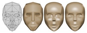
It’s an interesting way of improving visual quality that offers a simple migration path, since assets do not need to be heavily modified.
The PN Triangle evaluation consists of two steps: First, for every triangle of the input mesh a triangular cubic patch is derived solely from the vertex positions and normals; no adjacency information is required. Then, the resulting patch is subdivided or tessellated for rendering.p>
The resulting surface is smoother than the polygonal surface, but does not have tangent continuity in general, and that results in shading discontinuities. To hide these discontinuities normals are interpolated independently using either linear or quadratic interpolation. These normals are not the true surface normals, but they provide a smooth appearance to the surface.
This two-step evaluation maps very well to the Direct3D11 tessellation pipeline. The evaluation of the control points can be performed in the Hull Shader, the fixed function tessellator can produce a tessellation pattern in the triangle domain, and the actual surface can be evaluated for each of the tessellated vertices in the Domain Shader.
In order to support sharp edges a rim of small triangles is added along the edges. That increases the number of patches, and it’s not entirely clear how to properly texture map them.Scalar Tagged PN-Triangles solves that problem in a more elegant way by tagging each crease vertex with three scalar that act as shape controllers and modify the construction of the surface control points. However, this representation does not support crease corners.
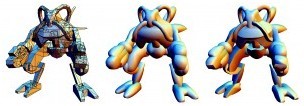
SILHOUETTE REFINEMENT
When tessellation is enabled the only supported primitive type is the patch primitive. In Direct3D11 a patch is an abstract primitive with an arbitrary number of vertices. You can use patches to represent traditional primitives (ie. a triangle is just a patch with 3 vertices), but this also enables you to represent other input primitives with arbitrary topology and additional connectivity information.
An interesting extension of of PN-Triangle tessellation is to augment the input triangles with the neighbor vertices in order to perform silhouetterefinement.
With this additional information it’s possible to compute tessellation factors in he Hull Shader based on whether an edge is on the silhouette or the interior of the mesh. Then the fixed function tessellator uses these edge tessellation factors to produce a semi-regular tessellation pattern and the Domain Shader transforms it to interpolate the surface.
PHONG TESSELLATION
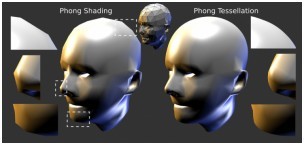
Phong Tessellation is a geometric version of Phong interpolation, but applied to vertex positions instead of normals.
First, points are interpolated linearly over each triangle using its barycentric coordinates, then the points are projected onto the planes defined by the corner position and normal, and finally the result of the three projections is interpolated again.
This procedure produces a smooth surface comparable to PN Triangles, but its evaluation is much cheaper, since no additional control points need to be computed.
BEZIER SURFACES
Curved surfaces are not only useful for characters, but also for level geometry and objects.
id Software introduced the use of quadratic Bezier patches for architectural geometry in Quake 3 Arena and has been using them ever since.
Climax Brighton’s Moto GP used cubic Bezier patches to model the motorcycles.
Bezier patches can be evaluated very efficiently, because they don’t need any information about the surrounding mesh. As these games show, tessellation hardware is not required to render these surfaces. However, hardware tessellation will allow doing it much more efficiently, and will facilitate the use of these and more complex surfaces.
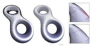
APPROXIMATION TO SUBDIVISION SURFACES
Rendering of approximated Catmull-Clark subdivision surfaces is probably the most anticipated application of hardware accelerated tessellation. Several approximation methods exist.
Approximating Catmull-Clark Subdivision Surfaces with Bicubic Patches is the most popular one. This approximation constructs a geometry patch and a pair of tangent patches for each quadrilateral face of the control mesh. The geometry patch approximates the shape and silhouette, but does not provide tangent continuity. A smooth normal field is constructed using two additional tangent patches. The approximation supports boundaries and has also been extended to support creases in Real-Time Creased Approximate Subdivision Surfaces.
GPU Smoothing of Quad Meshes proposes an alternative approximation using piecewise quartic triangular patches that have tangent continuity and do not require additional tangent patches to provide a smooth appearance. In Fast Parallel Construction of Smooth Surfaces from Meshes with Tri/Quad/Pent Facets the same approach is extended to approximate triangular and pentagonal faces.
Kenneth Scott, id Software
Gregory patches are a more compact representation that also provides a very similar approximation, but only support quad and triangle control faces.
The availability of sculpting tools like ZBrush and Mudbox makes it possible to create highly detailed meshes. Displaced subdivision surfaces provide a compact and efficient representation for these meshes.
RENDERING GEOMETRY IMAGES
Another approach to render highly detailed surfaces is to use geometry images. While geometry images can be rendered very efficiently, their video memory requirements are generally higher than displacement maps due to the lack of high precision texture compression formats. Traditional animation algorithms are not possible with this representation, and view dependent tessellation level evaluation is complicated, because geometry information is not directly available at the Hull Shader stage. However, geometry images may be the fastest approach to render small static objects at fixed tessellation levels.
TERRAIN RENDERING
Terrain rendering is one of the most obvious applications for tessellation. The flexibility of the tessellation pipeline enables the use of sophisticated algorithms to evaluate the level of refinement of the terrain patches, and frees you from having to worry about many of the implementation details.
It’s also possible to extend traditional terrain engines with arbitrary topologies. Some MMORPGs are already doing that to create more rich environments.
For example Saga of Ryzom, a game that is based on the Nevrax engine, uses cubic patches to model the terrain, which enables them to create impressive cliffs and overhangs.
Tessellation should make it possible to combine regular heightfields, with caves, cliffs, arches, and other interesting rock formations.
I think that ZBrush or Mudbox would be excellent tools to create natural looking rugged terrain.
HAIR RENDERING
Efficient hair rendering is one of the most interesting applications of the Direct3D11 tessellation pipeline. In addition to triangular and quad patches the fixed function tessellator can also generate lines, which are very useful for applications like hair and fur rendering.
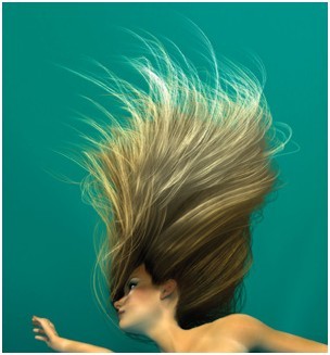
The algorithm described in Hair Animation and Rendering in the Nalu Demo maps very well to the tessellation pipeline.
As shown in Real-Time Rendering of Realistic Hair, the use of the hardware tessellation pipeline makes it very easy to simulate and render realistic hair with high geometric complexity in real-time.
That’s possible, because the simulation is performed only on a few hundred guide hairs, that are expanded by the tessellator into thousands of hair strands.
RENDERING PANORAMAS
Another application for tessellation is to perform arbitrary non linear projections, that is useful, for example, to create real-time panoramas.
Since graphics hardware relies on homogeneous linear interpolation for rasterization, arbitrary projections and deformations at the vertex level result in errors unless the surface is sufficiently refined.
The traditional image based approach is to render the scene to a cube map and then perform an arbitrary projection of the cubemap to screenspace relying on texture hardware to do the sampling and interpolation. This was the approach taken in Fisheye Quake and Pan quake.
While that works well, it requires rendering the scene to the 6 cube faces, and sometimes results in oversampling or undersampling of some areas of the scene.
Dynamic Mesh Refinement on GPU using Geometry Shaders proposes the use of the geometry shader to dynamically refine the surfaces to prevent linear interpolation artifacts. However, the Geometry Shader operates sequentially and is not well suited for this task. On the other side, the dynamic mesh refinement algorithm maps well to the Direct3D11 tessellation pipeline.
RENDERING OF 2D CURVED SHAPES
While GPUs can render simple polygons, they are not able to automatically handle complex concave and curved polygons with overlaps and self intersections, without prior triangulation and tessellation.

The Direct3D11 tessellation pipeline is not designed to perform triangulation. However, there’s a well known method to render arbitrary polygons using the stencil buffer that can be used in this case. This method was first described in theOpenGL Red Book, but was recently popularized by its implementation in the Qt graphic library.
It’s possible to combine this technique with hardware tessellation to render curved tessellated shapes without the need of expensive CPU tessellation and triangulation algorithms.