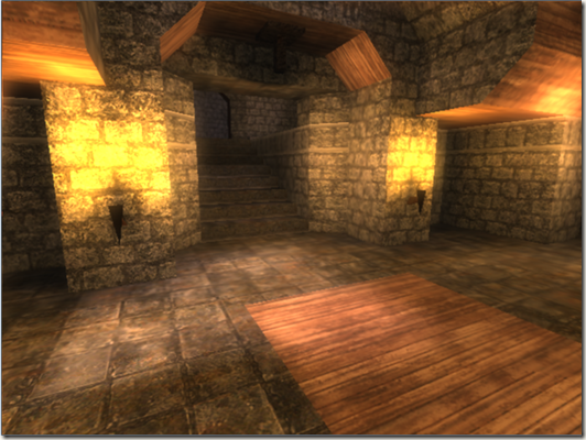
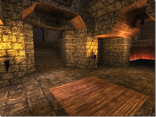
首先�Q�irrlicht的商业性是很浅的,如果要想应用于商业化�Q�不下一���d��夫是不行的�?比�v现在满天飞舞的UINTY3D�Q�就更不用说了。就���和OGRE比,也因为IRRLICHT没有提供太多花哨的特性,而导致这么多�q�来ARPU��g��直没有OGRE高,玩家���失率是巨大的�?/p>
Niko自己整的SupperCuber.���更不用说了�Q�我自己下蝲来弄了一下,也没见得有多好���Q�反正没有官方介�l�得那么牛B�?/p>
在重新定位自��p��深入挖掘的引擎之前,也曾再一�ơ被OGRE吸引�q��?原因有很多种�Q?/p>
一是天龙代码的泄漏�Q�里面有很多OGRE模型�Q�可以直接加载,构徏场景。很快速地获得像模像样的成���感�?/p>
二是�Q�OGRE本��n的DEMO���提供了大量的SHADER�Q�不用自己再辛辛苦苦地去东拼西找了�?/p>
三是�Q�本来与一个朋友相�U�用OGRE整RTS的, 因�ؓ目前公司的项目是RTS�Q�所以一旉����Q�对RTS兴趣大增�Q?看了0 A.D. GLEST�{�代码�?也明白了RTS中,工具与AI�Q�远�q�大�q�于画面昄����?所以,使用OGRE�Q�有现成的OgreCrowd�{�可以��用�?不用再�ؓ动态寻路找�ȝ���?/p>
四是�Q�OGRE的招聘和成熟的案例远�q�大于irrlicht. 光是我知道的 天龙八部�Q�成吉思汗�Q�独孤求败,极光世界�Q�火炬之光等�Q�就���_��说明它的威力�?/p>
五是�Q�OGRE官方支持WIN8,ADDROID,IOS。�?/p>
原因太多了,�q�是一���讲irrlicht的文章,老是夸OGRE是不道�d的�?/p>
下面�Q�我来说说我的原因,也供和我一��L���l�的朋友作一个参考�?/p>
一、我旉���有限�Q�虽然之前看�q�OGRE的代码,但是对OGRE�q�是不敢说有掌握�Q?如果要用OGRE�Q�其实还是得重头再来�?/p>
二、IRRLICHT因�ؓ东西不多�Q�所以以前在大学的时候,���对其很熟悉了,回过头来上手�Q�也更容易�?/p>
三、有一点点控制�Ʋ在里面�Q�想看看IRRLICHT�l�过攚w��后�Q�是不是真的比不上OGRE�?/p>
四、蜀门的成功�Q���够说明一个游戏的画面�Q�不是全部,只要不媄响大局�Q?有一个比较亮点的技术或者效果,���可以留住玩家�?我想�Q�蜀门里装备的流光效果,虽然���是�l�过���术�_�ֿ�设计后的�U�理动画�Q?但已�l���够体现高�U�装备和低��装备的差距�?玩家也能感受到自己高�U�装备的华丽�Q?所以,我更喜欢蜀门的�����y�?/p>
五、犯贱,���是多的人喜�Ƣ的东西�Q�越是不��x���?/p>
六、想慢慢�q�渡�Q�先使用IRRLICHT�Q�直到IRRLICHT不够用,���改�Q�改完了�Q�就把IRR所有的东西删除了,名字换了�?���是自己的了�?/p>
七、GAMELOFT的刺客信条用的是IRRLICHT�Q�所以,我觉得还是可以的�?�Q�PS:下蝲来玩了一下,在IPAD上,主角站立不动的时候,会来回抖动, 摄相机移动的时候,也会抖动�Q�很费解�Q?��N��是��Q点精度问题? 但UNITY3D和COCOS2D-X�{�是没有�q�问题的呀�Q��?/p>
其实�Q�列了很多条�Q�最后也发现�Q�IRRLICHT除了要简单点以外�Q�是没有OGRE那么强大的�?不过�Q�我�q�是选择了从����Q�毕竟精力有限�?如果要把OGRE整套东西理解了,再逐步重写�Q�我估计会疯掉�?毕竟大而全的东西,具体在用的时候,是要抛掉很多东西来换取效率的�?/p>
既然到这个点了,不得不说点别的�?/p>
11�q�的时候,公司研发的引擎在演示完DEMO后,���叫停了�?��目�q�行了两�q�半�Q�最后只有一堆代码和演示�E�序�?对公司来��_��其实是一定的损失�?后来��目�l�成员�{战WEB�?nbsp; 走到�q�一步,其实原来的成员只剩和我另一个搭档了�?/p>
没想刎ͼ��q�入了WEB�Q�就一��M��复返了�?�q�且�Q�公司的WEB��目�q�展也不是很��利�?nbsp; 都说毕业后两�q�是一个分水岭�Q?当时正好毕业两年�?于是军_��换一个环境挑战�?���来��C��目前的公司,做RTS游戏服务器�?nbsp; 面对未知的东西,貌似更能�Ȁ发我的兴���,如今马上又是一�q�了。渐渐地�Q�开始怀念引擎,怀念图形�?可以说IRRLICHT目前���是被我用来表达我对囑�Ş的思念�?虽然我图形方面的技术很陈旧�Q�老土�Q?但�ƈ不媄响我说我喜欢搞图形�?/p>
文章���到此吧。也不知道再要说些什么了�?/p>
�q�是使用freetype�q�行中文昄���的效果�?/p>
irrlicht�׃��是��用位囑֭�体的方式�Q�是很容易替换掉字体的�?同时�Q�其本��n也提供了Font接口替换的功能�?/p>
具体做法和网上大多数人是一��L���?/p>
在做�q�个的时候,又引入了另一个话题, gameswf和kfont(KlayGE Font)
gameswf是一个开源的C++ FLASH PLAYER�?/p>
gameloft以及很多�U�d��应用或者游戏都在��用它�?/p>
当然�Q�也包括ScaleForm. 因�ؓScaleForm是商业的�Q�所以比gameswf更加完善�Q�虽然说�Q�gameswf是ScaleForm的原型�?/p>
kfont一直是自己喜欢的一�U�字体解��x��案,其无比拉伸的能力非常讨�h喜欢。加上现在又单独成库了,如果不用gameswf的话�Q�我��x��它整合进irrlicht中�?两年前公司(先前的公司)的引擎就用上了这个,遗憾字体库不是我弄进�ȝ���Q�一直对kfont没有�q�距���L��触�?/p>
�|�上下蝲下来的代�?下面地址可供参考,�q�是我觉得众多文章中�Q�讲得比较细的一个�?/p>
http://blog.csdn.net/lee353086/article/details/5260101
至于FreeType,大家��d��方下载来�~�译���可以了�?/p>
BLOOM开
BLOOM�?/p>
在IRRLICHT中实现BLOOM�Q�和其它引擎中没有太多的不同�?SHADER�q�是那个SHADER�?/p>
关于BLOOM的算法,也就那样了,没有特别之处�Q�况且,我这BLOOM很暴�?/p>
render scene to texture.
1/4 downsample 选择暴光像素
h_blur 7�ơ采�?和权重��?
v_blur 7�ơ采�?和权重��?/p>
compose 两图叠加
下面说说我在irrlicht中实现post processing的方案�?/p>
在irrlicht中是没有屏幕寚w��四边形节点的�Q�如果要�Ҏ��扩展�Q�就只能修改代码了。我是尽量保证自�׃��修改IRR一行代码, 除非是真正��用时�Q�要�Ҏ��率进行优化。前现实现的GPU蒙皮�Q�水面,镜面�{�,都没有修改过一行代码, 因�ؓ我不惛_���������q��一旉���求,而改动了那一堆�?当我真的需要改动irrlicht才能辑ֈ�目标的时候,表示irrlicht中我使用的部分,可以退休了�?/p>
渲染场景的时候,我们通常在��用addXXXXSceneNode的时候,都默认不传父节点。这样就是默认的场景根节炏V��但是,当我们要做post process的时候,���需要对场景中的物体�q�行昄���的开和关�Q?于是�Q�我们�ؓ了很快速地控制�Q?于是���普通场景节点多加了一个父节点�Q?而post processing作�ؓ场景的兄弟节点, �q�样在渲染的时候,���可以方便地�q�行相关控制了�?/p>
大概是这��L��
RootSceneNode
PostProcessingNode SceneOjbectsNode
Obj1�?Obj2�?Obj3�?/p>
���程�Q?/p>
关闭 PostProcessingNode �Q?渲染 SceneOjbectsNode 下所有的物体到RT上�?/p>
关闭 SceneOjbectsNode�Q?打开PostProcessingNode�Q?�q�行一�p�d��的后期效果处理�?/p>
在irrlicht中是没有提供屏幕寚w��四边形绘制的�Q?如果手工构徏�Q�就很麻烦�?所以,我采用的是一�U�很常见的手法, 即通过UV坐标来计���最最�l�的��点坐标倹{�?/p>
VS的输出,是规一化坐标系�Q?即X,Y是处�?�Q�-1�Q?�Q�之间的�Q?于是�?我们只需�?pos = (uv-0.5)*2; pos.y = –pos.y;���可以了�?/p>
最�q�一直在加班�Q�没旉���整理��Z��码�?有兴���的朋友可以加下面的��?/p>
Irrlicht Engine-China
254431855
Posted on May 19, 2011, 11:00 pm, by xp, under Programming.
Just got a new Android phone (a Samsung Vibrant) a month ago, so after flashing a new ROM and installing a bunch of applications, what would I want to do with the new phone? Well, I’d like to know if the phone is fast enough to play 3D games. From the hardware configuration point of view, it is better equipped than my desktop computer in the 1990s, and since my desktop computer at the time had no problem with 3D games, I would expect it to be fast enough to do the same.
At first, I was considering downloading a 3D game from the market, but 3D games for Android are still rare, then why don’t I just create a 3D demo game myself?
After looking around which 3D game engines are available for the Android platform, I just settled down with Irrlicht. This is an open source C++ graphic engine, and not really a game engine per se, but it should have enough features to create my demo 3D application. And I like to have realistic physics in my game, so what could be better than the Bullet Physics library? This is the best known open source physics library, also developed in C++. The two libraries together would be an interesting combination.
Although Irrlicht was developed for desktop computers, but luckily enough, someone has already ported Irrlicht to the Android platform, which requires a special device driver for the graphic engine. And guess what? Someone has also created a Bullet wrapper for the Irrlicht engine. All of them in C++, and open source. All we need to do now to pull all these codes together to build a shared library for Android.
In this part, I’ll just describe what needs to compile all the codes for Android. Since we will compile C/C++ codes, you’ll need to download the Android native development kit. Please refer to the documentation on how to install.
We create an Android project, and add a jni folder. Then we put all the C/C++ source codes under the jni folder. I created three sub-folders:
- Bullet: All the Bullet Physics source codes. Actually, we only need the Collision, Dynamics, Soft Body and Linear Math libraries.
- Irrlicht: The Irrlicht 3D graphic engine source codes. This is the Android port of the engine.
- irrBullet: This is the Bullet wrapper for Irrlicht engine, which makes it easier to write your programs.
After, all we need to do is to create an Android.mk file, which is quite simple, really. You can read the makefile to see how it is structured. Basically, we just tell the Android NDK build tools that we want to build all the source codes for the Arm platform, and we want to link with the OpenGL ES library, to create a shared library called libirrlichtbullet.so. That’s about it.
However, there’s one minor thing to note though. Android does not really support C++ standard template library, but the irrBullet library made use of it. Therefore, in the jni folder, we need to add an Application.mk file, which contains the following line:
APP_STL := stlport_static
And that’s it. Now, you can run ndk-build to build the shared library. If you have a slow computer, it would take a while. If everything is alright, you should have a shared library in the folder libs/armeabi/. That shared library contains the Bullet Physics, Irrlicht and the irrBullet wrapper libraries. You can now create your 3D games for Android with it. In the next part, we will write a small demo program using this library.
You can download all the source codes and pre-built library here.
Programming 3D games on Android with Irrlicht and Bullet (Part 2)
Posted on May 20, 2011, 11:30 am, by xp, under Programming.
In the last post, we have built the Bullet Physics, Irrlicht and irrBullet libraries together to create a shared library for the Android platform. In this post, we are going to create a small demo 3D game for Android, using the libraries that we have built earlier.
This demo is not really anything new, I am going to just convert an Irrlicht example to run on Android. In this simple game, we are going to stack up a bunch of crates, and then we will shoot a sphere or a cube, from a distance, to topple the crates. The Irrlicht engine will handle all the 3D graphics, and the Bullet Physics library will take care of rigid body collision detection and all realistic physical kinetics. For example, when we shoot a sphere from the distance, how the sphere follows a curve line when flying over the air, how far it will fly, where it is going to fall on to the ground, how it reacts when it hits the ground, how it reacts when it hits the crates, and how the crates will react when being hit, etc, all these will be taken care of by Bullet Physics, and Irrlicht will render the game world accordingly.
Since it is easier to create Android project in Eclipse, we are going to work with Eclipse here. You will need to following tools to work with:
- Android SDK
- Android NDK
- Eclipse IDE
- Eclipse plugin for Android development.
I’m assuming you have all these tools installed and configured correctly. And I’m assuming you have basic knowledge on Android programming too, so I won’t get into the basic details here.
Let’s create a project called ca.renzhi.bullet, with an Activity called BulletActivity. The onCreate() method will look something like this:
-
@Override
-
public void onCreate(Bundle savedInstanceState) {
-
super.onCreate(savedInstanceState);
-
// Lock screen to landscape mode.
-
this.setRequestedOrientation(ActivityInfo.SCREEN_ORIENTATION_LANDSCAPE);
-
mGLView = new GLSurfaceView(getApplication());
-
renderer = new BulletRenderer(this);
-
mGLView.setRenderer(renderer);
-
DisplayMetrics displayMetrics = getResources().getDisplayMetrics();
-
width = displayMetrics.widthPixels;
-
height = displayMetrics.heightPixels;
-
setContentView(mGLView);
-
}
This just tells Android that we want an OpenGL surface view. We will create a Renderer class for this, something very simple like the following:
-
public class BulletRenderer implements Renderer
-
{
-
BulletActivity activity;
-
public BulletRenderer(BulletActivity activity)
-
{
-
this.activity = activity;
-
}
-
public void onDrawFrame(GL10 arg0)
-
{
-
activity.drawIteration();
-
}
-
public void onSurfaceChanged(GL10 gl, int width, int height)
-
{
-
activity.nativeResize(width, height);
-
}
-
public void onSurfaceCreated(GL10 gl, EGLConfig config)
-
{
-
activity.nativeInitGL(activity.width, activity.height);
-
}
-
}
The renderer class’s method will be invoked every time a frame needs to be rendered. There’s nothing special here. When the methods are invoked, we just invoke the native methods in the activity class, which will then call the C native functions through JNI. Since Irrlicht and Bullet are C++ libraries, we will have to write the main part of the game in C/C++. We keep very little logic in Java code.
When the surface is first created, the onSurfaceCreated() method is invoked, and here, we just call nativeInitGL(), which will initialize our game world in Irrlicht. This will initialize the device, the scene manager, create a physical world to manage the rigid bodies and their collision, create a ground floor, and put a stack of crates in the middle point. Then, we create a first-person-shooter (FPS) camera to look at the stack of crates. The player will look at this game world through the FPS camera.
I’m not going to describe the codes line by line, since you can download the codes to play with it. But when you create the Irrlicht device with the following line of code:
-
device = createDevice( video::EDT_OGLES1, dimension2d(gWindowWidth, gWindowHeight), 16, false, false, false, 0);
Make sure you select the correct version of OpenGL ES library on your Android device. I have version 1.x on mine. But if you have version 2.x, change to video::EDT_OGLES2 instead.
After the initialization, we would have a scene that looks like this:
When a frame is changed and needs to render, the onDrawFrame() method of the renderer is invoked. And here, we just call the nativeDrawIteration() function and will handle the game logic in C/C++ codes. The code looks like this:
-
void Java_ca_renzhi_bullet_BulletActivity_nativeDrawIteration(
-
JNIEnv* env,
-
jobject thiz,
-
jint direction,
-
jfloat markX, jfloat markY)
-
{
-
deltaTime = device->getTimer()->getTime() �?timeStamp;
-
timeStamp = device->getTimer()->getTime();
-
device->run();
-
// Step the simulation
-
world->stepSimulation(deltaTime * 0.001f, 120);
-
if ((direction != -1) || (markX != -1) || (markY != -1))
-
handleUserInput(direction, markX, markY);
-
driver->beginScene(true, true, SColor(0, 200, 200, 200));
-
smgr->drawAll();
-
guienv->drawAll();
-
driver->endScene();
-
}
As you can see, this is very standard Irrlicht game loop, the only thing added here is a function to handle user input.
User input includes moving left and right, forward and backward, shooting sphere and cube. Irrlicht engine depends on keyboard and mouse for user interaction, which are not available on Android devices. So, we will create a very basic kludge to allow users to move around and shoot. We will use touch and tap to handle user input. Users will move their finger left and right, on the left part of the screen, to move left and right in the game world. Users will move their finger up and down, on the right part of screen, to move forward and backward in the game world. And tap on the screen to shoot. Therefore, the movement direction is translated into a parameter, called direction, and passed to the native code to be handled. We also grab the X and Y coordinates of the shooting mark, and pass them as parameters to native codes as well.
That’s it. You can now build it, package into an apk, install it on your Android device, and play with it. When you shoot on the stack of crates, you would have a scene that looks like this:
The performance on my Samsung Vibrant is ok, I get about 56 or 57 FPS, which is quite smooth. But if there are too many objects to animate, especially after we have shot many spheres and cubes, we will have a screen that hangs and jumps a bit, or sometimes, it stops to react to user input for a fraction of second. In a real game, we might want to remove objects that have done their work, so that the number of objects to animate is significantly reduced to maintain an acceptable performance.
The other important thing that we want to improve is user interaction and control. The Irrlicht engine is developed for desktop computers, it relies mainly on keyboard and mouse for user interaction. These are not available on mobile devices. The current demo attempted to use touch and tap on screen as user control, but it does not work very well. In a next post, we will try to create virtual controls on screen (e.g. buttons, dials, etc), and we might want to take advantage of the sensor as well, which is a standard feature on mobile devices now.
You can download the source codes of the demo here.
Programming 3D games on Android with Irrlicht and Bullet (Part 3)
Posted on May 23, 2011, 6:25 pm, by xp, under Programming.
In the last post, we have created a basic 3D demo application with Irrlicht, in which we put a stack of crates, and we topple them by shooting a cube or a sphere.
In this post, we will try to create an on-screen control so that you can move around with it, like using a hardware control. What we want to have is something like this, in the following screenshot:
What we have here is a control knob, sitting on a base. The knob is in the centre of the base. The on-screen control always stays on top of the game scene, and the position should stay still regardless of how you move the camera. However, users can press on the knob, and drag it left and right, and this, in turn, moves the camera left and right accordingly.
Obviously, you can implement movement direction along more than one axis too. And you can also have more than one on-screen control if you want, since it is a device with multi-touch screen. But that’s left to you as an exercise.
Placing an on-screen control is actually quite easy. All you have to do is to load a picture as texture, then draw it as 2D image on the screen, at the location you want to put the control. But since we want the on-screen control to be always on top, we have to draw the 2D image after the game scene (and all the scene objects) are drawn. If we draw the 2D image first, it will hidden by the game scene. There, in your loop, you would have something like this:
-
driver->beginScene(true, true, SColor(0, 200, 200, 200));
-
smgr->drawAll();
-
guienv->drawAll();
-
// Draw the on-screen control now
-
onScreenControl->draw(driver);
-
driver->endScene();
That’s the basic idea. Here, we have created an OnScreenControl class, which encloses two objects, one of VirtualControlBase class and the other, of VirtualControlKnob class. The draw() method of the OnScreenControl class looks like this:
-
void OnScreenControl::draw(IVideoDriver* driver)
-
{
-
base->draw(driver);
-
knob->draw(driver);
-
}
It just relegates the drawing works to its sub-objects, the control base and the control knob. Note that the knob has to be drawn after the base, otherwise, it will be hidden behind the base, instead of sitting on top of it. The draw() method of the base looks like:
-
void VirtualControlBase::draw(IVideoDriver* driver)
-
{
-
driver->draw2DImage(_texture,
-
position2d(pos_x, pos_y),
-
rect(0, 0, width, height),
-
0,
-
SColor(255,255,255,255),
-
true);
-
}
As you see, it just draws a 2D image with the texture, at the location specified. That’s it.
After putting the on-screen control in place, we have to handle user touch events on the screen. If users press on the knob (i.e. pressing within the square boundary of the knob image), and move the finger around, we update the position of the knob according to the movement direction. Here, we want to make sure that users can not drag the knob out of the control base boundary (or too far out of the boundary anyway), to make it look and behave like a real control. As users move the knob around, you want to update your camera’s position accordingly. And when the knob is released, you want to reset its position back to the centre of the control base.
That’s basically the idea. You can grab the source code here. Ugly codes, I warn you.
The major problem of programming Irrlicht on Android is the separation of Java codes and the C/C++ codes. If you want to limit your program to only Android 2.3 or later, you can probably write the whole program in C/C++, using the native activity class. That way, you don’t have to move back and forth between Java and C++. But if you want to run your program on older versions of Android, your Activity must be written in Java, and the main game logic written in C/C++. You then have to catch user interaction events in your Java code, pass them through JNI to your C/C++ code. There will be loss of information as you move back and forth, not to mention that there will be quite a bit of code duplication. You can certainly create a full wrapper for the Irrlicht and Bullet libraries, but that will be taxing your mobile device heavily, and will certainly have a negative impact on performance. And creating a full wrapper for these two libraries would be a heck of a job.
The other problem is that, Irrlicht is an engine developed for the desktop, where keyboard and mouse are the main input devices. The Irrlicht port to Android mainly concerns with a display driver for Android, but the port has not really gone deep into this area of user interaction. Therefore, as you write your Irrlicht-based Android program, you would have to hack together user input handling model, event model, etc. In my demo, I haven’t even touched that, I have just kludged together some primitive event handling codes. In order to have our program fit in those multi-touch based devices, we would have to dig into the Irrlicht scene node animator and event handling mechanisms, and work it out from there. For example, we will have to define our own scene node animator which would be based on touch events instead of keyboard and mouse events, and add it to the scene node that we want to animate. This is something that we are going to look into in our future posts.
本来说是做镜子效果的�Q�结果手工计���的镜面反射矩阵应用在irrlicht相机上的时候,始终无法出现效果�Q�只能去�|�上搜烦
在irrlicht official wiki上发��C���q�个扩展的WaterNode�Q�下载下来,改了点BUG�Q�整合进了Terrain Demo里, ���是上图的效果�?/p>
在我的机器上,HLSL版本是没有问题的�Q�GL版本貌似RTT有点问题�?/p>
那就从今天这个用irrlicht做天龙八部的模型换装说�v吧�?/p>
也不知道是�ؓ什么,最�q�又捣鼓起了OGRE和irrlicht. �q�且�Q���L��用irrlicht实现一些OGRE中的东西�?/p>
当然�Q�这不是商业��目�Q�也没有商业目的�Q�纯属蛋��D��已�?/p>
一切行动的由来�Q�都来自于vczh那天晚上的�D动�?/p>
记得有一天晚上在���里聊天�Q�大伙就�U�赞各位菊苣是多么的厉害�?/p>
最后vc发了一个自��q��桌面截图��_��让你们看看菊苣是如何�l�成的(�q�不是原话,和话的字眼有出入�Q�在此不惌�����M��责�Q�Q�如果真有想看的�Q�去��ȝ��的聊天记录)
那天晚上�Q�我想了很久。想惌�����p��从�{做页�总�后,是如何虚渡光阴的�?/p>
�l�于忍不住了�Q�翻开了自��q���U�d�����盘�Q�看看自己曾�l�做�q�的���东�ѝ�?0%是徏好工�E�就没理了�?/p>
�q�才明白�Q�我花在思考上的时间远�q�大于了行动�?于是�Q�我军_��改变自己�Q�找回那个真的我�?/p>
3D游戏是我的真爱, 真爱到就���画面差一点,只要�?D�Q�我也会很喜�Ƣ�?/p>
于是�Q�我觉得自己�q�是应该接着先前的�\��C��厅R�?什么服务器�Q�什�?AS3. 都是���云�Q?不喜�Ƣ就是不喜欢�?/p>
�U�下又开始研�I�irrlicht了�?/p>
猛地一发现�Q�自己是多么的搞�W�, �?9�q�到11�q�_��一直在做引擎开发, 也翻�q�irrlicht和ogre无数遍�?却从来就没有写完�q�一个完整的DEMO�?/p>
�q�功能测试用例都没有写过。突然觉得之前的一些设计似乎有些脱���M��实际。没有真正��用过�Q�又怎知如何是好�Q�如何是坏呢�Q?/p>
�q�一�ơ是真的玩irrlicht了, 中间也纠�l�过是不是OGRE更适合�?但在目前�q�个旉���有限的空间下�Q�我更愿意玩irrlicht.�����y�Q�轻�ѝ�?当然�Q�意味着更多东西要自己实现�?不过对于一个代码控来说�Q�也反而更自得其乐�?正好可以在短路的时候,��d��考一下其它引擎,用来扩充irrlicht.
我要做的不是把irrlicht整得牛B�Q�而是惌���己弄弄,加上�U�d���q�_��的崛��P��我觉得irrlicht更加适合吧�?据说gameloft也有使用�Q�仅是据��_���?/p>
可能很多兄弟会说我这讲的东西�Q�其实就是一坨屎了�?不过�Q�我觉得再坏的评论,也表�C�Z���U�关注�?批评好过于无视啊~~~~
----------------------------------------------------------下面说说我遇上的�U�结------------------------------------------------
�U�结1:换装需要场景节炚w���?/strong>
在irrlicht中,�q�没有提供普通引擎中的submesh或者bodypart�q�种东西�Q�用于直接支持换装�?在irrlicht中,如果惌���换装�Q�最直接的方法就是依赖于场景�l�点
比如,在我的示例中�Q�可以更换头发,帽子�Q�衣服,护腕�Q�靴子,面容�?那就需�?个场景节点,1个作为根节点�Q�用于控制整个角色的世界坐标�Q���^�U�,�~�放�Q�旋转等属性。另�?个场景节点则分别�l�有各个部�g的模�?/p>
贴一下我的角色类的代码,行数不多
class CCharactor
{
IrrlichtDevice* m_pDevice;
IAnimatedMeshSceneNode* m_pBodyParts[eCBPT_Num];
ISceneNode* m_pRoot;
public:
CCharactor(IrrlichtDevice* pDevice)
:m_pDevice(pDevice)
{
memset(m_pBodyParts,0,sizeof(m_pBodyParts));
m_pRoot = pDevice->getSceneManager()->addEmptySceneNode(NULL,12345);
}
void changeBodyPart(ECharactorBodyPartType ePartType,stringw& meshPath,stringw& metrialPath)
{
ISceneManager* smgr = m_pDevice->getSceneManager();
IAnimatedMeshSceneNode* pBpNode = m_pBodyParts[ePartType];
IAnimatedMesh* pMesh = smgr->getMesh(meshPath.c_str());
if(pMesh==NULL)
return;
if(pBpNode==NULL)
{
pBpNode = smgr->addAnimatedMeshSceneNode(pMesh,m_pRoot);
m_pBodyParts[ePartType] = pBpNode;
}
else
{
pBpNode->setMesh(pMesh);
}
ITexture* pTexture = m_pDevice->getVideoDriver()->getTexture(metrialPath.c_str());
if(pTexture)
pBpNode->setMaterialTexture(0,pTexture);
}
};
//然后�Q�我用了一个结构体来构建部件信�?/p>
struct SBodyPartInfo
{
stringw Desc;
ECharactorBodyPartType Type;
stringw MeshPath;
stringw MeterialPath;
};
�U�结2�Q�共享骨�?/strong>
首先�Q�irrlicht 1.8中对OGRE模型的格式支持在代码中,最高只看到�?.40版本的解析,更高的就会被无视�?天龙八部的模型有几个�?.30的,而用于换装和主角的,都是1.40的�?可能是解析不全的原因�Q�导�?.40的骨骼动��L��法正常播放�?�q�个问题整了几个���时�Q�没有解冻I��明天�l�箋
其次�Q�多个模型共享骨骼只能通过场景节点的useAnimationFrom来完成,�q�且传入的是一个Mesh参数。这点让�������|�� 天龙八部的角色动作是分开了的�Q�不同的��d��动作是一个skeleton文�g�?惌���实现�׃�n�Q�有炚w��烦�?/p>
�U�结3�Q�模型文件格�?/strong>
irrlicht不像OGRE那样有一个强大且成熟的模型文件格�?虽然提供�?irr格式�Q�但仅是用于irrEdit的场景信息输出。先看一张图
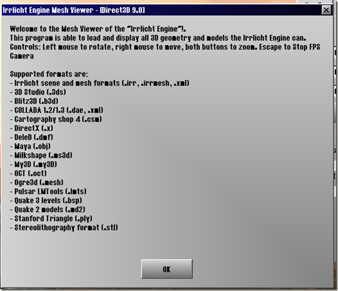
�q�张图是irrlicht samples中的MeshViewer的提�C�框内容�?上面列出了可以支持的模型文�g�c�d���?大家可以看看�Q�又有多���模型格式是可以直接拿来攑ֈ���目上用的呢�Q?mdl和ms3d可以考虑�Q�dae的话�Q�我在开源游�? A.D. 中见��C��用过�?其它的话�Q�就完全不熟悉了�?OGRE�?.mesh支持也不完全�?��N��真要自己整一个�?
我能惛_��的,���是选一个插件完整和模型和动��L��式都比较好的作�ؓ与美术工具交互的格式�?自己再写一个工��P��转换成自��q��格式�?/p>
�U�结4�Q�硬件蒙�?/strong>
我以为像NIKO那样的技术狂�Q�怎么会放掉这一个特性�?很高兴地在场景节点上发现了硬件蒙皮的函数接口。但一看注释,把我咽着了�?/p>
//! (This feature is not implemented in irrlicht yet)
virtual bool setHardwareSkinning(bool on);
其它地方�Q�还没有��L���Q�就先不发表�a���Z���?�l�箋着�q�个很傻B,很天真的捣鼓之�\�?
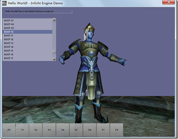
上个图,�U�念一下我的irrlicht产物�?/p>
布衣
换了�w�盔�?/p>
换了帽子和靴�?/p>
PS:头发没有�U�理�Q�所以是白的�?/p>


