Visualize Surface by Delaunay Triangulator
eryar@163.com
Abstract. Delaunay Triangulation is the core algorithm for mesh generation. By Delaunay Triangulator you can make a general method to visualize geometry surfaces, so does OpenCascade. The paper focus on the geometry surfaces visualization, include the surfaces with holes.
Key words. OpenCascade, Delaunay Triangulator, OpenSceneGraph, Mesh, NURBS
1. Introduction
模型數(shù)據(jù)最終要在顯示器上輸出,需要有統(tǒng)一的處理方法。對于曲線而言,只需要在曲線上取一定的點(diǎn)連接成線,就可以用來逼近顯示曲線了。對于曲面而言,可以用三角網(wǎng)格來逼近曲面。對于參數(shù)表示的曲線,求曲線的點(diǎn)很容易,只要給出參數(shù)就可以得到參數(shù)對應(yīng)的曲線上的點(diǎn)。對于參數(shù)表示的曲面,情況要復(fù)雜些了,如何得到三角網(wǎng)格呢?
經(jīng)過boolean operation后,會有些孔產(chǎn)生,這些面上的孔如何用統(tǒng)一的方法可視化呢?對于曲面的可視化也一定存在統(tǒng)一、簡單的方法。程序開發(fā)最終追求的都是簡單、統(tǒng)一,這樣代碼才顯得優(yōu)雅。如果代碼看上去很復(fù)雜,到處是重復(fù)代碼,暴露出來的接口也很隨意,完全違背單一職責(zé)原則和Demeter法則,開發(fā)出來的軟件用起來必定也很麻煩,這對程序員和軟件用戶都是噩夢。這樣的代碼一定有重構(gòu)和改進(jìn)的空間,最終達(dá)到程序開發(fā)人員和軟件的用戶都舒服的狀態(tài)。書山有路勤為徑,學(xué)海無涯苦作舟,拒絕保守、懶惰,不思進(jìn)取。
言歸正傳,本文主要使用OpenSceneGraph中的Delaunay Triangulator來對OpenCascade中的任意參數(shù)曲面可視化,即曲面可視化的統(tǒng)一算法。在理解曲面可視化的基礎(chǔ)上,可對NURBS曲面的可視化,有助于直觀來學(xué)習(xí)NURBS理論。
談到NURBS理論,又是追求統(tǒng)一、簡單的產(chǎn)物。由于在數(shù)學(xué)和算法上的良好性質(zhì),以及在工業(yè)領(lǐng)域的成功應(yīng)用,使得NURBS得到了極大的普及。NURBS在CAD/CAM/CAE領(lǐng)域中所起的作用類似于英語在科學(xué)和商業(yè)中的作用。因此,想從事CAD,必須理解NURBS。NURBS的重要作用就是統(tǒng)一了曲線曲面的數(shù)學(xué)模型,使軟件對曲線曲面的處理方式相同,且利用NURBS進(jìn)行設(shè)計(jì)非常直觀,幾乎每個(gè)工具和算法都有一個(gè)易于理解的幾何解釋。
讓CAD軟件用戶使用簡單,得到便利,就要有相應(yīng)的技術(shù)(NURBS)支持。至于NURBS是Non-Uniform Rational B-Spline還是Nobody Understands Rational B-Spline,普通用戶是不關(guān)心的。網(wǎng)格化的算法也是類似,讓三維模型可視化變得簡單、統(tǒng)一,至于是使用Delaunay Triangulation還是其他算法,對于圖形顯示接口如OpenGL也不關(guān)心,他只管畫三角形就好。然而高效的網(wǎng)格化算法也是一個(gè)技術(shù)難點(diǎn)。如果不僅要知其然而且還要知其所以然,都要付出努力。
2. Visualize Geometry Surface
網(wǎng)格生成技術(shù)是研究如何將給定的空間離散為簡單的幾何單元的方法。三角網(wǎng)格和四面體網(wǎng)格是迄今為止最為常用的非結(jié)構(gòu)形式,它可以很好地逼近邊界,描述結(jié)構(gòu)復(fù)雜的空間。Delaunay三角、四面體剖分由于其具有良好的數(shù)學(xué)基礎(chǔ),對網(wǎng)格的局部控制能力強(qiáng),網(wǎng)格單元自動向正三角、四面體逼近等優(yōu)良特性,近年來受到了眾多領(lǐng)域的研究人員的關(guān)注,在科學(xué)計(jì)算可視化、圖形學(xué)三維表示、石油地質(zhì)勘探、地理信息系統(tǒng)、逆向工程、醫(yī)學(xué)圖像處理等領(lǐng)域有著明顯的應(yīng)用前景。
在數(shù)字地形建模中,不規(guī)則三角網(wǎng)(TIN)通過從不規(guī)則離散分布的數(shù)據(jù)點(diǎn)生成的連續(xù)三角面來逼近地形表面。就表達(dá)地形信息角度而言,TIN模型的優(yōu)點(diǎn)是它能以不同層次的分辨率來描述地形表面。TIN模型在一定特定分辨率下能用更少的空間和時(shí)間更精確地表示復(fù)雜的表面。特別是當(dāng)?shù)匦伟写罅刻卣鳎鐢嗔丫€、構(gòu)造線時(shí),TIN模型能更好地顧及這些特征,從而更精確地表達(dá)地表形態(tài)。關(guān)于Delaunay算法,可以參考相關(guān)書籍或網(wǎng)絡(luò)資源自己實(shí)現(xiàn),或是使用開源庫,如Triangle, CGAL等。本文主要是使用OpenSceneGraph中現(xiàn)成算法來將參數(shù)曲面可視化。
OpenSceneGraph中Delaunay的使用非常簡單,只需要將點(diǎn)集傳給DelaunayTriangulator即可,下面代碼示例將OpenCascade中任意參數(shù)曲面的參數(shù)空間離散成三角網(wǎng)格,再映射到三維空間,將曲面可視化。
osg::Node* BuildSurface(const Handle_Geom_Surface &theSurface)
{
osg::ref_ptr<osg::Geode> aGeode = new osg::Geode();
osg::ref_ptr<osg::Geometry> aGeometry = new osg::Geometry();
osg::ref_ptr<osg::Vec3Array> aUVPoints = new osg::Vec3Array();
osg::ref_ptr<osg::Vec3Array> aPoints = new osg::Vec3Array();
osg::ref_ptr<osgUtil::DelaunayTriangulator> dt = new osgUtil::DelaunayTriangulator();
// build triangulation for the parametric space.
Standard_Real u1 = 0.0;
Standard_Real u2 = 0.0;
Standard_Real v1 = 0.0;
Standard_Real v2 = 0.0;
theSurface->Bounds(u1, u2, v1, v2);
Precision::IsNegativeInfinite(u1) ? u1 = -1.0: u1;
Precision::IsPositiveInfinite(u2) ? u2 = 1.0: u2;
Precision::IsNegativeInfinite(v1) ? v1 = -1.0: v1;
Precision::IsPositiveInfinite(v2) ? v2 = 1.0: v2;
// tesselate the parametric space.
Standard_Integer aStep = 30;
Standard_Real uDelta = (u2 - u1) / aStep;
Standard_Real vDelta = (v2 - v1) / aStep;
for (Standard_Integer i = 0; i <= aStep; ++i)
{
for (Standard_Integer j = 0; j <= aStep; ++j)
{
Standard_Real u = u1 + i * uDelta;
Standard_Real v = v1 + j * vDelta;
aUVPoints->push_back(osg::Vec3(u, v, 0.0));
}
}
// triangulate the parametric space.
dt->setInputPointArray(aUVPoints);
dt->triangulate();
for (osg::Vec3Array::const_iterator j = aUVPoints->begin(); j != aUVPoints->end(); ++j)
{
// evaluate the point on the surface
gp_Pnt aPoint = theSurface->Value((*j).x(), (*j).y());
aPoints->push_back(osg::Vec3(aPoint.X(), aPoint.Y(), aPoint.Z()));
}
//aGeometry->setVertexArray(aUVPoints);
aGeometry->setVertexArray(aPoints);
aGeometry->addPrimitiveSet(dt->getTriangles());
aGeode->addDrawable(aGeometry);
// use smoothing visitor to set the average normals
osgUtil::SmoothingVisitor sv;
sv.apply(*aGeode);
// set material for the surface
osg::ref_ptr<osg::StateSet> aStateSet = aGeode->getOrCreateStateSet();
osg::ref_ptr<osg::Material> aMaterial = new osg::Material();
aMaterial->setDiffuse(osg::Material::FRONT, osg::Vec4(1.0f, 1.0f, 0.0f, 1.0f));
aMaterial->setSpecular(osg::Material::FRONT, osg::Vec4(1.0f, 1.0f, 1.0f, 1.0f));
aMaterial->setShininess(osg::Material::FRONT, 100.0f);
aStateSet->setAttribute(aMaterial);
return aGeode.release();
}
為了與另一篇blog中的區(qū)別,在OpenSceneGraph中繪制OpenCascade的曲面: http://www.shnenglu.com/eryar/archive/2013/08/11/202466.html
特意加上了材質(zhì)和光照效果。離散的曲面效果如下圖所示:
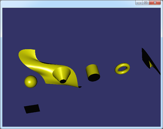
Figure 2.1 Shaded Surfaces in OpenSceneGraph
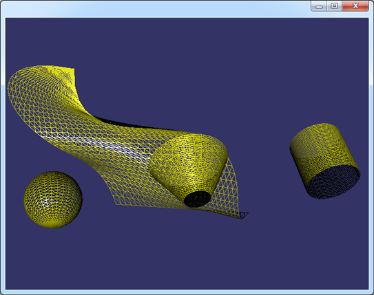
Figure 2.2 Mesh of the Surfaces in OpenSceneGraph
為了顯示出光照效果,使用了osgUtil::SmoothingVisitor來自動計(jì)算三角網(wǎng)格的平均法向。從上圖可知,這種方式是將曲面的參數(shù)空間均勻剖分得到的曲面,當(dāng)剖分得密時(shí),數(shù)據(jù)量大,但顯示得逼真。剖分疏時(shí),數(shù)據(jù)量小,顯示失真。
利用特征敏感網(wǎng)格重剖技術(shù),可以使用較少的三角面片來比較精確地表示幾何模型,如下圖所示:(圖片來源:http://cg.cs.tsinghua.edu.cn/papers/TVCG2007featuresensitive.pdf)
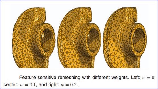
Figure 2.3 Feature sensitive remeshing (http://cg.cs.tsinghua.edu.cn/)
3. Holes in the Surface
當(dāng)曲面上有開孔時(shí),開孔的信息可以通過WIRE來獲得。對于組成開孔的WIRE的每條EDGE,可以通過曲面上的曲線PCurve來將開孔的參數(shù)統(tǒng)一到曲面的UV參數(shù)空間。
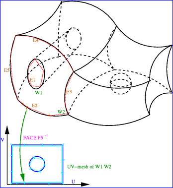
Figure 3.1 Hole in Parametric UV space
在OpenSceneGraph中實(shí)現(xiàn)代碼如下所示:
osg::Node* BuildSurface(const Handle_Geom_Surface &theSurface, const Handle_Geom2d_Curve &thePCurve)
{
osg::ref_ptr<osg::Geode> aGeode = new osg::Geode();
osg::ref_ptr<osg::Geometry> aGeometry = new osg::Geometry();
osg::ref_ptr<osg::Vec3Array> aUVPoints = new osg::Vec3Array();
osg::ref_ptr<osg::Vec3Array> aPoints = new osg::Vec3Array();
osg::ref_ptr<osg::Vec3Array> aBounds = new osg::Vec3Array();
osg::ref_ptr<osgUtil::DelaunayTriangulator> dt = new osgUtil::DelaunayTriangulator();
osg::ref_ptr<osgUtil::DelaunayConstraint> dc = new osgUtil::DelaunayConstraint();
// build triangulation for the parametric space.
Standard_Real u1 = 0.0;
Standard_Real u2 = 0.0;
Standard_Real v1 = 0.0;
Standard_Real v2 = 0.0;
theSurface->Bounds(u1, u2, v1, v2);
Precision::IsNegativeInfinite(u1) ? u1 = -1.0: u1;
Precision::IsPositiveInfinite(u2) ? u2 = 1.0: u2;
Precision::IsNegativeInfinite(v1) ? v1 = -1.0: v1;
Precision::IsPositiveInfinite(v2) ? v2 = 1.0: v2;
// tesselate the parametric space.
Standard_Integer aStep = 30;
Standard_Real uDelta = (u2 - u1) / aStep;
Standard_Real vDelta = (v2 - v1) / aStep;
for (Standard_Integer i = 0; i <= aStep; ++i)
{
for (Standard_Integer j = 0; j <= aStep; ++j)
{
Standard_Real u = u1 + i * uDelta;
Standard_Real v = v1 + j * vDelta;
aUVPoints->push_back(osg::Vec3(u, v, 0.0));
}
}
Standard_Real pDelta = (thePCurve->LastParameter() - thePCurve->FirstParameter()) / aStep;
for (Standard_Integer c = 0; c <= aStep; ++c)
{
gp_Pnt2d p = thePCurve->Value(thePCurve->FirstParameter () + c * pDelta);
aBounds->push_back(osg::Vec3(p.X(), p.Y(), 0.0));
}
dc->setVertexArray(aBounds);
dc->addPrimitiveSet(new osg::DrawArrays(osg::PrimitiveSet::LINE_LOOP, 0, aBounds->size()));
// triangulate the parametric space.
dt->addInputConstraint(dc);
dt->setInputPointArray(aUVPoints);
dt->triangulate();
dt->removeInternalTriangles(dc);
for (osg::Vec3Array::const_iterator j = aUVPoints->begin(); j != aUVPoints->end(); ++j)
{
// evaluate the point on the surface
gp_Pnt aPoint = theSurface->Value((*j).x(), (*j).y());
aPoints->push_back(osg::Vec3(aPoint.X(), aPoint.Y(), aPoint.Z()));
}
//aGeometry->setVertexArray(aUVPoints);
aGeometry->setVertexArray(aPoints);
aGeometry->addPrimitiveSet(dt->getTriangles());
aGeode->addDrawable(aGeometry);
// use smoothing visitor to set the average normals
osgUtil::SmoothingVisitor sv;
sv.apply(*aGeode);
// set material for the surface
osg::ref_ptr<osg::StateSet> aStateSet = aGeode->getOrCreateStateSet();
osg::ref_ptr<osg::Material> aMaterial = new osg::Material();
aMaterial->setDiffuse(osg::Material::FRONT, osg::Vec4(1.0f, 1.0f, 0.0f, 1.0f));
aMaterial->setSpecular(osg::Material::FRONT, osg::Vec4(1.0f, 1.0f, 1.0f, 1.0f));
aMaterial->setShininess(osg::Material::FRONT, 100.0f);
aStateSet->setAttribute(aMaterial);
return aGeode.release();
}
開孔的實(shí)現(xiàn)主要也是用osgUtil::DelaunayConstraint,將孔中的三角形去除。如下圖所示為在球面和錐面開孔:
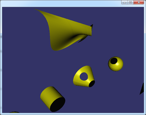
Figure 3.2 Holes on Sphere and Cone Surface
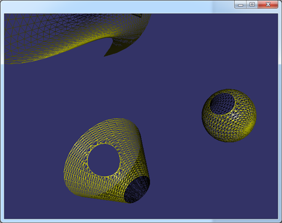
Figure 3.3 Mesh for Sphere and Cone with holes
由上圖可知,對于有拓樸結(jié)構(gòu)的三維模型數(shù)據(jù),可以由WIRE得到組成孔的每條邊Edge,根據(jù)Edge中PCurve可以找到對應(yīng)的曲面。通過PCurve將開孔數(shù)據(jù)統(tǒng)一到參數(shù)空間中。剖分完帶孔的參數(shù)空間,再映射回三維空間就得到開孔的曲面了。
4. Conclusion
原來一直百思不得其解的問題現(xiàn)在已經(jīng)豁然開朗,對三維模型的可視化有了一定的理解。借助于這些開源庫,對相關(guān)知識的學(xué)習(xí)要輕松許多,可以將許多國產(chǎn)教材上斷續(xù)的理論知識與實(shí)踐銜接起來。
5. Acknowledgement
感謝OpenCascade和OpenSceneGraph的開放和分享,讓學(xué)習(xí)變得輕松有趣。
6. Reference
1. 孫家廣, 胡事民等. 計(jì)算機(jī)圖形學(xué). 清華大學(xué)出版社. 2000
2. 趙罡, 穆國旺, 王拉柱譯. 非均勻有理B樣條. 清華大學(xué)出版社. 2010
3. Jonathan R. Shewchuk. Triangle: http://www.cs.cmu.edu/~quake/triangle.html
4. 汪嘉業(yè) 王文平 屠長河 楊承磊. 計(jì)算幾何及應(yīng)用. 科學(xué)出版社. 2011
5. 王成恩. 面向科學(xué)計(jì)算的網(wǎng)格劃分與可視化技術(shù). 科學(xué)出版社. 2011
6. 周培德. 計(jì)算幾何-算法設(shè)計(jì)與分析. 清華大學(xué)出版社. 2008
7. http://cg.cs.tsinghua.edu.cn/
8. Mesh Algorithm in OpenCascade:
http://www.shnenglu.com/eryar/archive/2014/04/06/206484.html