提示:
閱讀本文需要一定的3D圖形學和DirectX9基礎,如果你發現閱讀困難,請參閱D3D
中基本三角形面的繪制。
本文用到的坐標系統變換函數請參閱DirectX
9的坐標系統變換。
頂點順序和背面剔除
在世界空間中,面向攝影機的三維物體的剖分三角形面為前面,是可視的;背向攝影機的三角形面稱為背面,是不可視的。對于可視的前面進行渲染顯示,對于不可視的背面則不進行渲染處理,這就是所謂的背面剔除。
為了省去繁雜的前面和背面的計算判斷,DirectX將依據寫入頂點緩沖區的三角形面3個頂點的順(逆)時針方向來定義該面為前面或背面,以直接規定三角形面是否顯示。在DirectX的默認情形下,如果寫入頂點緩沖區的三角形面的3
個頂點為順時針方向,那么這3個頂點構成的三角形面被認為是前面,必須進行渲染顯示。相反,如果3個頂點的順序為反時針,則為背面三角形,不需要渲染處理。
為了判斷三角形面(v0, v1, v2)三個頂點的順(逆)時針方向,可計算三角形面的法向量(v1 - v0) x (v2 -
v0),然后根據法向量與攝影機的視線方向向量的點積的符號來判斷,負號表示三個頂點是順時針方向,正號表示三個頂點是逆時針方向。由此可見,三角形面頂點的順序相當于直接給出了該面的外向法向量的方向。只有外向法向量指向攝影機的一側,三角形面才被顯示,否則將被剔除而不做顯示。
利用IDirect3DDevice9接口的SetRenderState函數可修改或重新設置Direct3D設備的背面剔除的渲染狀態,當然該函數的功能是十分豐富的,不局限于設置背面剔除狀態,來看看函數說明:
Sets a single device render-state parameter.
HRESULT SetRenderState(
  D3DRENDERSTATETYPE State,
  DWORD Value
);
Parameters
- State
- [in] Device state variable that is being modified. This parameter can be
any member of the D3DRENDERSTATETYPE enumerated type.
- Value
- [in] New value for the device render state to be set. The meaning of
this parameter is dependent on the value specified for State. For
example, if State were D3DRS_SHADEMODE, the second parameter would be
one member of the D3DSHADEMODE enumerated type.
Return Values
If the method succeeds, the return value is D3D_OK. D3DERR_INVALIDCALL is
returned if one of the arguments is invalid.
我們來看看參數State使用的
D3DRENDERSTATETYPE類型的詳細信息:
Render states define set-up states for all kinds of vertex and pixel
processing. Some render states set up vertex processing, and some set up pixel
processing (see Render States (Direct3D 9)). Render states can be saved and
restored using stateblocks (see State Blocks Save and Restore State (Direct3D
9)).
typedef enum D3DRENDERSTATETYPE
{
    D3DRS_ZENABLE = 7,
    D3DRS_FILLMODE = 8,
    D3DRS_SHADEMODE = 9,
    D3DRS_ZWRITEENABLE = 14,
    D3DRS_ALPHATESTENABLE = 15,
    D3DRS_LASTPIXEL = 16,
    D3DRS_SRCBLEND = 19,
    D3DRS_DESTBLEND = 20,
    D3DRS_CULLMODE = 22,
    D3DRS_ZFUNC = 23,
    D3DRS_ALPHAREF = 24,
    D3DRS_ALPHAFUNC = 25,
    D3DRS_DITHERENABLE = 26,
    D3DRS_ALPHABLENDENABLE = 27,
    D3DRS_FOGENABLE = 28,
    D3DRS_SPECULARENABLE = 29,
    D3DRS_FOGCOLOR = 34,
    D3DRS_FOGTABLEMODE = 35,
    D3DRS_FOGSTART = 36,
    D3DRS_FOGEND = 37,
    D3DRS_FOGDENSITY = 38,
    D3DRS_RANGEFOGENABLE = 48,
    D3DRS_STENCILENABLE = 52,
    D3DRS_STENCILFAIL = 53,
    D3DRS_STENCILZFAIL = 54,
    D3DRS_STENCILPASS = 55,
    D3DRS_STENCILFUNC = 56,
    D3DRS_STENCILREF = 57,
    D3DRS_STENCILMASK = 58,
    D3DRS_STENCILWRITEMASK = 59,
    D3DRS_TEXTUREFACTOR = 60,
    D3DRS_WRAP0 = 128,
    D3DRS_WRAP1 = 129,
    D3DRS_WRAP2 = 130,
    D3DRS_WRAP3 = 131,
    D3DRS_WRAP4 = 132,
    D3DRS_WRAP5 = 133,
    D3DRS_WRAP6 = 134,
    D3DRS_WRAP7 = 135,
    D3DRS_CLIPPING = 136,
    D3DRS_LIGHTING = 137,
    D3DRS_AMBIENT = 139,
    D3DRS_FOGVERTEXMODE = 140,
    D3DRS_COLORVERTEX = 141,
    D3DRS_LOCALVIEWER = 142,
    D3DRS_NORMALIZENORMALS = 143,
    D3DRS_DIFFUSEMATERIALSOURCE = 145,
    D3DRS_SPECULARMATERIALSOURCE = 146,
    D3DRS_AMBIENTMATERIALSOURCE = 147,
    D3DRS_EMISSIVEMATERIALSOURCE = 148,
    D3DRS_VERTEXBLEND = 151,
    D3DRS_CLIPPLANEENABLE = 152,
    D3DRS_POINTSIZE = 154,
    D3DRS_POINTSIZE_MIN = 155,
    D3DRS_POINTSPRITEENABLE = 156,
    D3DRS_POINTSCALEENABLE = 157,
    D3DRS_POINTSCALE_A = 158,
    D3DRS_POINTSCALE_B = 159,
    D3DRS_POINTSCALE_C = 160,
    D3DRS_MULTISAMPLEANTIALIAS = 161,
    D3DRS_MULTISAMPLEMASK = 162,
    D3DRS_PATCHEDGESTYLE = 163,
    D3DRS_DEBUGMONITORTOKEN = 165,
    D3DRS_POINTSIZE_MAX = 166,
    D3DRS_INDEXEDVERTEXBLENDENABLE = 167,
    D3DRS_COLORWRITEENABLE = 168,
    D3DRS_TWEENFACTOR = 170,
    D3DRS_BLENDOP = 171,
    D3DRS_POSITIONDEGREE = 172,
    D3DRS_NORMALDEGREE = 173,
    D3DRS_SCISSORTESTENABLE = 174,
    D3DRS_SLOPESCALEDEPTHBIAS = 175,
    D3DRS_ANTIALIASEDLINEENABLE = 176,
    D3DRS_MINTESSELLATIONLEVEL = 178,
    D3DRS_MAXTESSELLATIONLEVEL = 179,
    D3DRS_ADAPTIVETESS_X = 180,
    D3DRS_ADAPTIVETESS_Y = 181,
    D3DRS_ADAPTIVETESS_Z = 182,
    D3DRS_ADAPTIVETESS_W = 183,
    D3DRS_ENABLEADAPTIVETESSELLATION = 184,
    D3DRS_TWOSIDEDSTENCILMODE = 185,
    D3DRS_CCW_STENCILFAIL = 186,
    D3DRS_CCW_STENCILZFAIL = 187,
    D3DRS_CCW_STENCILPASS = 188,
    D3DRS_CCW_STENCILFUNC = 189,
    D3DRS_COLORWRITEENABLE1 = 190,
    D3DRS_COLORWRITEENABLE2 = 191,
    D3DRS_COLORWRITEENABLE3 = 192,
    D3DRS_BLENDFACTOR = 193,
    D3DRS_SRGBWRITEENABLE = 194,
    D3DRS_DEPTHBIAS = 195,
    D3DRS_WRAP8 = 198,
    D3DRS_WRAP9 = 199,
    D3DRS_WRAP10 = 200,
    D3DRS_WRAP11 = 201,
    D3DRS_WRAP12 = 202,
    D3DRS_WRAP13 = 203,
    D3DRS_WRAP14 = 204,
    D3DRS_WRAP15 = 205,
    D3DRS_SEPARATEALPHABLENDENABLE = 206,
    D3DRS_SRCBLENDALPHA = 207,
    D3DRS_DESTBLENDALPHA = 208,
    D3DRS_BLENDOPALPHA = 209,
    D3DRS_FORCE_DWORD = 0x7fffffff,
} D3DRENDERSTATETYPE, *LPD3DRENDERSTATETYPE;
Constants
- D3DRS_ZENABLE
- Depth-buffering state as one member of the D3DZBUFFERTYPE enumerated
type. Set this state to D3DZB_TRUE to enable z-buffering, D3DZB_USEW to
enable w-buffering, or D3DZB_FALSE to disable depth buffering.
The default value for this render state is D3DZB_TRUE if a depth stencil
was created along with the swap chain by setting the EnableAutoDepthStencil
member of the D3DPRESENT_PARAMETERS structure to TRUE, and D3DZB_FALSE
otherwise.
- D3DRS_FILLMODE
- One or more members of the D3DFILLMODE enumerated type. The default
value is D3DFILL_SOLID.
- D3DRS_SHADEMODE
- One or more members of the D3DSHADEMODE enumerated type. The default
value is D3DSHADE_GOURAUD.
- D3DRS_ZWRITEENABLE
- TRUE to enable the application to write to the depth buffer. The default
value is TRUE. This member enables an application to prevent the system from
updating the depth buffer with new depth values. If FALSE, depth comparisons
are still made according to the render state D3DRS_ZFUNC, assuming that
depth buffering is taking place, but depth values are not written to the
buffer.
- D3DRS_ALPHATESTENABLE
- TRUE to enable per pixel alpha testing. If the test passes, the pixel is
processed by the frame buffer. Otherwise, all frame-buffer processing is
skipped for the pixel.
The test is done by comparing the incoming alpha value with the reference
alpha value, using the comparison function provided by the D3DRS_ALPHAFUNC
render state. The reference alpha value is determined by the value set for
D3DRS_ALPHAREF. For more information, see Alpha Testing State (Direct3D 9).
The default value of this parameter is FALSE.
- D3DRS_LASTPIXEL
- The default value is TRUE, which enables drawing of the last pixel in a
line. To prevent drawing of the last pixel, set this value to FALSE. For
more information, see Outline and Fill State (Direct3D 9).
- D3DRS_SRCBLEND
- One member of the D3DBLEND enumerated type. The default value is
D3DBLEND_ONE.
- D3DRS_DESTBLEND
- One member of the D3DBLEND enumerated type. The default
value is D3DBLEND_ZERO.
- D3DRS_CULLMODE
- Specifies how back-facing triangles are culled, if at all. This can be
set to one member of the D3DCULL enumerated type. The default value is
D3DCULL_CCW.
- D3DRS_ZFUNC
- One member of the D3DCMPFUNC enumerated type. The default value is
D3DCMP_LESSEQUAL. This member enables an application to accept or reject a
pixel, based on its distance from the camera.
The depth value of the pixel is compared with the depth-buffer value. If
the depth value of the pixel passes the comparison function, the pixel is
written.
The depth value is written to the depth buffer only if the render state
is TRUE.
Software rasterizers and many hardware accelerators work faster if the
depth test fails, because there is no need to filter and modulate the
texture if the pixel is not going to be rendered.
- D3DRS_ALPHAREF
- Value that specifies a reference alpha value against which pixels are
tested when alpha testing is enabled. This is an 8-bit value placed in the
low 8 bits of the DWORD render-state value. Values can range from 0x00000000
through 0x000000FF. The default value is 0.
- D3DRS_ALPHAFUNC
- One member of the D3DCMPFUNC enumerated type. The
default value is D3DCMP_ALWAYS. This member enables an application to accept
or reject a pixel, based on its alpha value.
- D3DRS_DITHERENABLE
- TRUE to enable dithering. The default value is FALSE.
- D3DRS_ALPHABLENDENABLE
- TRUE to enable alpha-blended transparency. The default value is FALSE.
The type of alpha blending is determined by the D3DRS_SRCBLEND and
D3DRS_DESTBLEND render states.
- D3DRS_FOGENABLE
- TRUE to enable fog blending. The default value is FALSE. For more
information about using fog blending, see Fog.
- D3DRS_SPECULARENABLE
- TRUE to enable specular highlights. The default value is FALSE.
Specular highlights are calculated as though every vertex in the object
being lit is at the object's origin. This gives the expected results as long
as the object is modeled around the origin and the distance from the light
to the object is relatively large. In other cases, the results as undefined.
When this member is set to TRUE, the specular color is added to the base
color after the texture cascade but before alpha blending.
- D3DRS_FOGCOLOR
- Value whose type is D3DCOLOR. The default value is 0. For more
information about fog color, see Fog Color (Direct3D 9).
- D3DRS_FOGTABLEMODE
- The fog formula to be used for pixel fog. Set to one of the members of
the D3DFOGMODE enumerated type. The default value is D3DFOG_NONE. For more
information about pixel fog, see Pixel Fog (Direct3D 9).
- D3DRS_FOGSTART
- Depth at which pixel or vertex fog effects begin for linear fog mode.
The default value is 0.0f. Depth is specified in world space for vertex fog
and either device space [0.0, 1.0] or world space for pixel fog. For pixel
fog, these values are in device space when the system uses z for fog
calculations and world-world space when the system is using eye-relative fog
(w-fog). For more information, see Fog Parameters (Direct3D 9) and
Eye-Relative vs. Z-based Depth.
Values for the this render state are floating-point values. Because the
IDirect3DDevice9::SetRenderState method accepts DWORD values, your
application must cast a variable that contains the value, as shown in the
following code example.
pDevice9->SetRenderState(D3DRS_FOGSTART,
                         *((DWORD*) (&fFogStart)));
- D3DRS_FOGEND
- Depth at which pixel or vertex fog effects end for linear fog mode. The
default value is 1.0f. Depth is specified in world space for vertex fog and
either device space [0.0, 1.0] or world space for pixel fog. For pixel fog,
these values are in device space when the system uses z for fog calculations
and in world space when the system is using eye-relative fog (w-fog). For
more information, see Fog Parameters (Direct3D 9) and
Eye-Relative vs. Z-based Depth.
Values for this render state are floating-point values. Because the
IDirect3DDevice9::SetRenderState method accepts DWORD
values, your application must cast a variable that contains the value, as
shown in the following code example.
m_pDevice9->SetRenderState(D3DRS_FOGEND, *((DWORD*) (&fFogEnd)));
- D3DRS_FOGDENSITY
- Fog density for pixel or vertex fog used in the exponential fog modes
(D3DFOG_EXP and D3DFOG_EXP2). Valid density values range from 0.0 through
1.0. The default value is 1.0. For more information, see Fog
Parameters (Direct3D 9).
Values for this render state are floating-point values. Because the
IDirect3DDevice9::SetRenderState method accepts DWORD
values, your application must cast a variable that contains the value, as
shown in the following code example.
m_pDevice9->SetRenderState(D3DRS_FOGDENSITY, *((DWORD*) (&fFogDensity)));
- D3DRS_RANGEFOGENABLE
- TRUE to enable range-based vertex fog. The default value is FALSE, in
which case the system uses depth-based fog. In range-based fog, the distance
of an object from the viewer is used to compute fog effects, not the depth
of the object (that is, the z-coordinate) in the scene. In range-based fog,
all fog methods work as usual, except that they use range instead of depth
in the computations.
Range is the correct factor to use for fog computations, but depth is
commonly used instead because range is time-consuming to compute and depth
is generally already available. Using depth to calculate fog has the
undesirable effect of having the fogginess of peripheral objects change as
the viewer's eye moves - in this case, the depth changes and the range
remains constant.
Because no hardware currently supports per-pixel range-based fog, range
correction is offered only for vertex fog.
For more information, see Vertex Fog (Direct3D 9).
- D3DRS_STENCILENABLE
- TRUE to enable stenciling, or FALSE to disable stenciling. The default
value is FALSE. For more information, see Stencil Buffer Techniques
(Direct3D 9).
- D3DRS_STENCILFAIL
- Stencil operation to perform if the stencil test fails. Values are from
the D3DSTENCILOP enumerated type. The default value is D3DSTENCILOP_KEEP.
- D3DRS_STENCILZFAIL
- Stencil operation to perform if the stencil test passes and the depth
test (z-test) fails. Values are from the D3DSTENCILOP
enumerated type. The default value is D3DSTENCILOP_KEEP.
- D3DRS_STENCILPASS
- Stencil operation to perform if both the stencil and the depth (z) tests
pass. Values are from the D3DSTENCILOP enumerated type. The
default value is D3DSTENCILOP_KEEP.
- D3DRS_STENCILFUNC
- Comparison function for the stencil test. Values are from the
D3DCMPFUNC enumerated type. The default value is D3DCMP_ALWAYS.
The comparison function is used to compare the reference value to a
stencil buffer entry. This comparison applies only to the bits in the
reference value and stencil buffer entry that are set in the stencil mask
(set by the D3DRS_STENCILMASK render state). If TRUE, the stencil test
passes.
- D3DRS_STENCILREF
- An int reference value for the stencil test. The default value is 0.
- D3DRS_STENCILMASK
- Mask applied to the reference value and each stencil buffer entry to
determine the significant bits for the stencil test. The default mask is
0xFFFFFFFF.
- D3DRS_STENCILWRITEMASK
- Write mask applied to values written into the stencil buffer. The
default mask is 0xFFFFFFFF.
- D3DRS_TEXTUREFACTOR
- Color used for multiple-texture blending with the D3DTA_TFACTOR
texture-blending argument or the D3DTOP_BLENDFACTORALPHA texture-blending
operation. The associated value is a D3DCOLOR variable. The
default value is opaque white (0xFFFFFFFF).
- D3DRS_WRAP0
- Texture-wrapping behavior for multiple sets of texture coordinates.
Valid values for this render state can be any combination of the
D3DWRAPCOORD_0 (or D3DWRAP_U), D3DWRAPCOORD_1 (or D3DWRAP_V), D3DWRAPCOORD_2
(or D3DWRAP_W), and D3DWRAPCOORD_3 flags. These cause the system to wrap in
the direction of the first, second, third, and fourth dimensions, sometimes
referred to as the s, t, r, and q directions, for a given texture. The
default value for this render state is 0 (wrapping disabled in all
directions).
- D3DRS_WRAP1
- See D3DRS_WRAP0.
- D3DRS_WRAP2
- See D3DRS_WRAP0.
- D3DRS_WRAP3
- See D3DRS_WRAP0.
- D3DRS_WRAP4
- See D3DRS_WRAP0.
- D3DRS_WRAP5
- See D3DRS_WRAP0.
- D3DRS_WRAP6
- See D3DRS_WRAP0.
- D3DRS_WRAP7
- See D3DRS_WRAP0.
- D3DRS_CLIPPING
- TRUE to enable primitive clipping by Direct3D, or FALSE to disable it.
The default value is TRUE.
- D3DRS_LIGHTING
- TRUE to enable Direct3D lighting, or FALSE to disable it. The default
value is TRUE. Only vertices that include a vertex normal are properly lit;
vertices that do not contain a normal employ a dot product of 0 in all
lighting calculations.
- D3DRS_AMBIENT
- Ambient light color. This value is of type D3DCOLOR.
The default value is 0.
- D3DRS_FOGVERTEXMODE
- Fog formula to be used for vertex fog. Set to one member of the
D3DFOGMODE enumerated type. The default value is D3DFOG_NONE.
- D3DRS_COLORVERTEX
- TRUE to enable per-vertex color or FALSE to disable it. The default
value is TRUE. Enabling per-vertex color allows the system to include the
color defined for individual vertices in its lighting calculations.
For more information, see the following render states:
- D3DRS_DIFFUSEMATERIALSOURCE
- D3DRS_SPECULARMATERIALSOURCE
- D3DRS_AMBIENTMATERIALSOURCE
- D3DRS_EMISSIVEMATERIALSOURCE
- D3DRS_LOCALVIEWER
- TRUE to enable camera-relative specular highlights, or FALSE to use
orthogonal specular highlights. The default value is TRUE. Applications that
use orthogonal projection should specify false.
- D3DRS_NORMALIZENORMALS
- TRUE to enable automatic normalization of vertex normals, or FALSE to
disable it. The default value is FALSE. Enabling this feature causes the
system to normalize the vertex normals for vertices after transforming them
to camera space, which can be computationally time-consuming.
- D3DRS_DIFFUSEMATERIALSOURCE
- Diffuse color source for lighting calculations. Valid values are members
of the D3DMATERIALCOLORSOURCE enumerated type. The default value is
D3DMCS_COLOR1. The value for this render state is used only if the
D3DRS_COLORVERTEX render state is set to TRUE.
- D3DRS_SPECULARMATERIALSOURCE
- Specular color source for lighting calculations. Valid values are
members of the D3DMATERIALCOLORSOURCE enumerated type. The
default value is D3DMCS_COLOR2.
- D3DRS_AMBIENTMATERIALSOURCE
- Ambient color source for lighting calculations. Valid values are members
of the D3DMATERIALCOLORSOURCE enumerated type. The default
value is D3DMCS_MATERIAL.
- D3DRS_EMISSIVEMATERIALSOURCE
- Emissive color source for lighting calculations. Valid values are
members of the D3DMATERIALCOLORSOURCE enumerated type. The
default value is D3DMCS_MATERIAL.
- D3DRS_VERTEXBLEND
- Number of matrices to use to perform geometry blending, if any. Valid
values are members of the D3DVERTEXBLENDFLAGS enumerated type. The default
value is D3DVBF_DISABLE.
- D3DRS_CLIPPLANEENABLE
- Enables or disables user-defined clipping planes. Valid values are any
DWORD in which the status of each bit (set or not set) toggles the
activation state of a corresponding user-defined clipping plane. The least
significant bit (bit 0) controls the first clipping plane at index 0, and
subsequent bits control the activation of clipping planes at higher indexes.
If a bit is set, the system applies the appropriate clipping plane during
scene rendering. The default value is 0.
The D3DCLIPPLANEn macros are defined to provide a convenient way to
enable clipping planes.
- D3DRS_POINTSIZE
- A float value that specifies the size to use for point size computation
in cases where point size is not specified for each vertex. This value is
not used when the vertex contains point size. This value is in screen space
units if D3DRS_POINTSCALEENABLE is FALSE; otherwise this value is in world
space units. The default value is the value a driver returns. If a driver
returns 0 or 1, the default value is 64, which allows software point size
emulation. Because the IDirect3DDevice9::SetRenderState
method accepts DWORD values, your application must cast a variable that
contains the value, as shown in the following code example.
m_pDevice9->SetRenderState(D3DRS_POINTSIZE, *((DWORD*)&pointSize));
- D3DRS_POINTSIZE_MIN
- A float value that specifies the minimum size of point primitives. Point
primitives are clamped to this size during rendering. Setting this to values
smaller than 1.0 results in points dropping out when the point does not
cover a pixel center and antialiasing is disabled or being rendered with
reduced intensity when antialiasing is enabled. The default value is 1.0f.
The range for this value is greater than or equal to 0.0f. Because the
IDirect3DDevice9::SetRenderState method accepts DWORD
values, your application must cast a variable that contains the value, as
shown in the following code example.
m_pDevice9->SetRenderState(D3DRS_POINTSIZE_MIN, *((DWORD*)&pointSizeMin));
- D3DRS_POINTSPRITEENABLE
- bool value. When TRUE, texture coordinates of point primitives are set
so that full textures are mapped on each point. When FALSE, the vertex
texture coordinates are used for the entire point. The default value is
FALSE. You can achieve DirectX 7 style single-pixel points by setting
D3DRS_POINTSCALEENABLE to FALSE and D3DRS_POINTSIZE to 1.0, which are the
default values.
- D3DRS_POINTSCALEENABLE
- bool value that controls computation of size for point primitives. When
TRUE, the point size is interpreted as a camera space value and is scaled by
the distance function and the frustum to viewport y-axis scaling to compute
the final screen-space point size. When FALSE, the point size is interpreted
as screen space and used directly. The default value is FALSE.
- D3DRS_POINTSCALE_A
- A float value that controls for distance-based size attenuation for
point primitives. Active only when D3DRS_POINTSCALEENABLE is TRUE. The
default value is 1.0f. The range for this value is greater than or equal to
0.0f. Because the IDirect3DDevice9::SetRenderState method
accepts DWORD values, your application must cast a variable that contains
the value, as shown in the following code example.
m_pDevice9->SetRenderState(D3DRS_POINTSCALE_A, *((DWORD*)&pointScaleA));
- D3DRS_POINTSCALE_B
- A float value that controls for distance-based size attenuation for
point primitives. Active only when D3DRS_POINTSCALEENABLE is TRUE. The
default value is 0.0f. The range for this value is greater than or equal to
0.0f. Because the IDirect3DDevice9::SetRenderState method
accepts DWORD values, your application must cast a variable that contains
the value, as shown in the following code example.
m_pDevice9->SetRenderState(D3DRS_POINTSCALE_B, *((DWORD*)&pointScaleB));
- D3DRS_POINTSCALE_C
- A float value that controls for distance-based size attenuation for
point primitives. Active only when D3DRS_POINTSCALEENABLE is TRUE. The
default value is 0.0f. The range for this value is greater than or equal to
0.0f. Because the IDirect3DDevice9::SetRenderState method
accepts DWORD values, your application must cast a variable that contains
the value, as shown in the following code example.
m_pDevice9->SetRenderState(D3DRS_POINTSCALE_C, *((DWORD*)&pointScaleC));
- D3DRS_MULTISAMPLEANTIALIAS
- bool value that determines how individual samples are computed when
using a multisample render-target buffer. When set to TRUE, the multiple
samples are computed so that full-scene antialiasing is performed by
sampling at different sample positions for each multiple sample. When set to
FALSE, the multiple samples are all written with the same sample value,
sampled at the pixel center, which allows non-antialiased rendering to a
multisample buffer. This render state has no effect when rendering to a
single sample buffer. The default value is TRUE.
- D3DRS_MULTISAMPLEMASK
- Each bit in this mask, starting at the least significant bit (LSB),
controls modification of one of the samples in a multisample render target.
Thus, for an 8-sample render target, the low byte contains the eight write
enables for each of the eight samples. This render state has no effect when
rendering to a single sample buffer. The default value is 0xFFFFFFFF.
This render state enables use of a multisample buffer as an accumulation
buffer, doing multipass rendering of geometry where each pass updates a
subset of samples.
If there are n multisamples and k enabled samples, the resulting
intensity of the rendered image should be k/n. Each component RGB of every
pixel is factored by k/n.
- D3DRS_PATCHEDGESTYLE
- Sets whether patch edges will use float style tessellation. Possible
values are defined by the D3DPATCHEDGESTYLE enumerated type. The default
value is D3DPATCHEDGE_DISCRETE.
- D3DRS_DEBUGMONITORTOKEN
- Set only for debugging the monitor. Possible values are defined by the
D3DDEBUGMONITORTOKENS enumerated type. Note that if D3DRS_DEBUGMONITORTOKEN
is set, the call is treated as passing a token to the debug monitor. For
example, if - after passing D3DDMT_ENABLE or D3DDMT_DISABLE to
D3DRS_DEBUGMONITORTOKEN - other token values are passed in, the state
(enabled or disabled) of the debug monitor will still persist.
This state is only useful for debug builds. The debug monitor defaults to
D3DDMT_ENABLE.
- D3DRS_POINTSIZE_MAX
- A float value that specifies the maximum size to which point sprites
will be clamped. The value must be less than or equal to the MaxPointSize
member of D3DCAPS9 and greater than or equal to D3DRS_POINTSIZE_MIN. The
default value is 64.0. Because the IDirect3DDevice9::SetRenderState
method accepts DWORD values, your application must cast a variable that
contains the value, as shown in the following code example.
m_pDevice9->SetRenderState(D3DRS_PONTSIZE_MAX, *((DWORD*)&pointSizeMax));
- D3DRS_INDEXEDVERTEXBLENDENABLE
- bool value that enables or disables indexed vertex blending. The default
value is FALSE. When set to TRUE, indexed vertex blending is enabled. When
set to FALSE, indexed vertex blending is disabled. If this render state is
enabled, the user must pass matrix indices as a packed DWORDwith every
vertex. When the render state is disabled and vertex blending is enabled
through the D3DRS_VERTEXBLEND state, it is equivalent to having matrix
indices 0, 1, 2, 3 in every vertex.
- D3DRS_COLORWRITEENABLE
- UINT value that enables a per-channel write for the render-target color
buffer. A set bit results in the color channel being updated during 3D
rendering. A clear bit results in the color channel being unaffected. This
functionality is available if the D3DPMISCCAPS_COLORWRITEENABLE capabilities
bit is set in the PrimitiveMiscCaps member of the D3DCAPS9
structure for the device. This render state does not affect the clear
operation. The default value is 0x0000000F.
Valid values for this render state can be any combination of the
D3DCOLORWRITEENABLE_ALPHA, D3DCOLORWRITEENABLE_BLUE,
D3DCOLORWRITEENABLE_GREEN, or D3DCOLORWRITEENABLE_RED flags.
- D3DRS_TWEENFACTOR
- A float value that controls the tween factor. The default value is 0.0f.
Because the IDirect3DDevice9::SetRenderState method accepts
DWORD values, your application must cast a variable that contains the value,
as shown in the following code example.
m_pDevice9->SetRenderState(D3DRS_TWEENFACTOR, *((DWORD*)&TweenFactor));
- D3DRS_BLENDOP
- Value used to select the arithmetic operation applied when the alpha
blending render state, D3DRS_ALPHABLENDENABLE, is set to TRUE. Valid values
are defined by the D3DBLENDOP enumerated type. The default value is
D3DBLENDOP_ADD.
If the D3DPMISCCAPS_BLENDOP device capability is not supported, then
D3DBLENDOP_ADD is performed.
- D3DRS_POSITIONDEGREE
- N-patch position interpolation degree. The values can be D3DDEGREE_CUBIC
(default) or D3DDEGREE_LINEAR. For more information, see D3DDEGREETYPE.
- D3DRS_NORMALDEGREE
- N-patch normal interpolation degree. The values can be D3DDEGREE_LINEAR
(default) or D3DDEGREE_QUADRATIC. For more information, see
D3DDEGREETYPE.
- D3DRS_SCISSORTESTENABLE
- TRUE to enable scissor testing and FALSE to disable it. The default
value is FALSE.
- D3DRS_SLOPESCALEDEPTHBIAS
- Used to determine how much bias can be applied to co-planar primitives
to reduce z-fighting. The default value is 0.
bias = (max * D3DRS_SLOPESCALEDEPTHBIAS) + D3DRS_DEPTHBIAS.
where max is the maximum depth slope of the triangle being rendered.
- D3DRS_ANTIALIASEDLINEENABLE
TRUE to enable line antialiasing, FALSE to disable line antialiasing. The
default value is FALSE.
- When rendering to a multisample render target,
D3DRS_ANTIALIASEDLINEENABLE is ignored and all lines are rendered aliased.
Use ID3DXLine for antialiased line rendering in a multisample render target.
- D3DRS_MINTESSELLATIONLEVEL
- Minimum tessellation level. The default value is 1.0f. See Tessellation
(Direct3D 9).
- D3DRS_MAXTESSELLATIONLEVEL
- Maximum tessellation level. The default value is 1.0f. See
Tessellation (Direct3D 9).
- D3DRS_ADAPTIVETESS_X
- Amount to adaptively tessellate, in the x direction. Default value is
0.0f. See Adaptive Tessellation.
- D3DRS_ADAPTIVETESS_Y
- Amount to adaptively tessellate, in the y direction. Default value is
0.0f. See Adaptive_Tessellation.
- D3DRS_ADAPTIVETESS_Z
- Amount to adaptively tessellate, in the z direction. Default value is
1.0f. See Adaptive_Tessellation.
- D3DRS_ADAPTIVETESS_W
- Amount to adaptively tessellate, in the w direction. Default value is
0.0f. See Adaptive_Tessellation.
- D3DRS_ENABLEADAPTIVETESSELLATION
- TRUE to enable adaptive tessellation, FALSE to disable it. The default
value is FALSE. See Adaptive_Tessellation.
- D3DRS_TWOSIDEDSTENCILMODE
TRUE enables two-sided stenciling, FALSE disables it. The default value
is FALSE. The application should set D3DRS_CULLMODE to D3DCULL_NONE to
enable two-sided stencil mode. If the triangle winding order is clockwise,
the D3DRS_STENCIL* operations will be used. If the winding order is
counterclockwise, the D3DRS_CCW_STENCIL* operations will be used.
- To see if two-sided stencil is supported, check the StencilCaps member
of D3DCAPS9 for D3DSTENCILCAPS_TWOSIDED. See also
D3DSTENCILCAPS.
- D3DRS_CCW_STENCILFAIL
- Stencil operation to perform if CCW stencil test fails. Values are from
the D3DSTENCILOP enumerated type. The default value is
D3DSTENCILOP_KEEP.
- D3DRS_CCW_STENCILZFAIL
- Stencil operation to perform if CCW stencil test passes and z-test
fails. Values are from the D3DSTENCILOP enumerated type.
The default value is D3DSTENCILOP_KEEP.
- D3DRS_CCW_STENCILPASS
- Stencil operation to perform if both CCW stencil and z-tests pass.
Values are from the D3DSTENCILOP enumerated type. The
default value is D3DSTENCILOP_KEEP.
- D3DRS_CCW_STENCILFUNC
- The comparison function. CCW stencil test passes if ((ref & mask)
stencil function (stencil & mask)) is true. Values are from the
D3DCMPFUNC enumerated type. The default value is D3DCMP_ALWAYS.
- D3DRS_COLORWRITEENABLE1
- Additional ColorWriteEnable values for the devices. See
D3DRS_COLORWRITEENABLE. This functionality is available if the
D3DPMISCCAPS_INDEPENDENTWRITEMASKS capabilities bit is set in the
PrimitiveMiscCaps member of the D3DCAPS9 structure for the
device. The default value is 0x0000000f.
- D3DRS_COLORWRITEENABLE2
- Additional ColorWriteEnable values for the devices. See
D3DRS_COLORWRITEENABLE. This functionality is available if the
D3DPMISCCAPS_INDEPENDENTWRITEMASKS capabilities bit is set in the
PrimitiveMiscCaps member of the D3DCAPS9 structure for the
device. The default value is 0x0000000f.
- D3DRS_COLORWRITEENABLE3
- Additional ColorWriteEnable values for the devices. See
D3DRS_COLORWRITEENABLE. This functionality is available if the
D3DPMISCCAPS_INDEPENDENTWRITEMASKS capabilities bit is set in the
PrimitiveMiscCaps member of the D3DCAPS9 structure for the
device. The default value is 0x0000000f.
- D3DRS_BLENDFACTOR
- D3DCOLOR used for a constant blend-factor during alpha
blending. This functionality is available if the D3DPBLENDCAPS_BLENDFACTOR
capabilities bit is set in the SrcBlendCaps member of D3DCAPS9
or the DestBlendCaps member of D3DCAPS9. See
D3DRENDERSTATETYPE. The default value is 0xffffffff.
- D3DRS_SRGBWRITEENABLE
- Enable render-target writes to be gamma corrected to sRGB. The format
must expose D3DUSAGE_SRGBWRITE. The default value is 0.
- D3DRS_DEPTHBIAS
- A floating-point value that is used for comparison of depth values. See
Depth Bias (Direct3D 9). The default value is 0.
- D3DRS_WRAP8
- See D3DRS_WRAP0.
- D3DRS_WRAP9
- See D3DRS_WRAP0.
- D3DRS_WRAP10
- See D3DRS_WRAP0.
- D3DRS_WRAP11
- See D3DRS_WRAP0.
- D3DRS_WRAP12
- See D3DRS_WRAP0.
- D3DRS_WRAP13
- See D3DRS_WRAP0.
- D3DRS_WRAP14
- See D3DRS_WRAP0.
- D3DRS_WRAP15
- See D3DRS_WRAP0.
- D3DRS_SEPARATEALPHABLENDENABLE
TRUE enables the separate blend mode for the alpha channel. The default
value is FALSE.
- When set to false, the render-target blending factors and operations
applied to alpha are forced to be the same as those defined for color. This
mode is effectively hardwired to false on implementations that don't set the
cap D3DPMISCCAPS_SEPARATEALPHABLEND. See D3DPMISCCAPS.
The type of separate alpha blending is determined by the
D3DRS_SRCBLENDALPHA and D3DRS_DESTBLENDALPHA render states.
- D3DRS_SRCBLENDALPHA
- One member of the D3DBLEND enumerated type. This value
is ignored unless D3DRS_SEPARATEALPHABLENDENABLE is true. The default value
is D3DBLEND_ONE.
- D3DRS_DESTBLENDALPHA
- One member of the D3DBLEND enumerated type. This value
is ignored unless D3DRS_SEPARATEALPHABLENDENABLE is true. The default value
is D3DBLEND_ZERO.
- D3DRS_BLENDOPALPHA
Value used to select the arithmetic operation applied to separate alpha
blending when the render state, D3DRS_SEPARATEALPHABLENDENABLE, is set to
TRUE.
- Valid values are defined by the D3DBLENDOP enumerated
type. The default value is D3DBLENDOP_ADD.
If the D3DPMISCCAPS_BLENDOP device capability is not supported, then
D3DBLENDOP_ADD is performed. See D3DPMISCCAPS.
- D3DRS_FORCE_DWORD
- Forces this enumeration to compile to 32 bits in size. Without this
value, some compilers would allow this enumeration to compile to a size
other than 32 bits. This value is not used.
Remarks
| Render States |
| ps_1_1 to ps_1_3 |
4 texture samplers |
Direct3D defines the D3DRENDERSTATE_WRAPBIAS constant as a convenience for
applications to enable or disable texture wrapping, based on the zero-based
integer of a texture coordinate set (rather than explicitly using one of the
D3DRS_WRAP n state values). Add the D3DRENDERSTATE_WRAPBIAS value to the
zero-based index of a texture coordinate set to calculate the D3DRS_WRAP n value
that corresponds to that index, as shown in the following example.
// Enable U/V wrapping for textures that use the texture
// coordinate set at the index within the dwIndex variable
HRESULT hr = pd3dDevice->SetRenderState(dwIndex + D3DRENDERSTATE_WRAPBIAS, D3DWRAPCOORD_0 | D3DWRAPCOORD_1);
// If dwIndex is 3, the value that results from
// the addition equals D3DRS_WRAP3 (131)
這個函數的功能太復雜了,有時間可以慢慢研究。
頂點索引緩沖區
通常,為了渲染顯示三維物體的各個微小三角形面,必須重復將頂點寫入頂點緩沖區中。為了解決重復寫入的頂點將會占用大量內存的問題,先創建一個頂點緩沖區,將不重復的頂點數據寫入,然后創建一個頂點索引緩沖區,存放三維物體各微分三角形面的頂點索引信息。這種方法同樣給出了完整的三維物體的三角形面的組成信息。
頂點索引緩沖區可用Direct3D設備的CreateIndexBuffer函數來創建:
Creates an index buffer.
HRESULT CreateIndexBuffer(
  UINT Length,
  DWORD Usage,
  D3DFORMAT Format,
  D3DPOOL Pool,
  IDirect3DIndexBuffer9** ppIndexBuffer,
  HANDLE* pSharedHandle
);
Parameters
- Length
- [in] Size of the index buffer, in bytes.
- Usage
- [in] Usage can be 0, which indicates no usage value. However, if usage
is desired, use a combination of one or more D3DUSAGE constants. It is good
practice to match the usage parameter in CreateIndexBuffer with the behavior
flags in IDirect3D9::CreateDevice. For more information, see Remarks.
- Format
- [in] Member of the D3DFORMAT enumerated type, describing the format of
the index buffer. For more information, see Remarks. The valid settings are
the following:
- D3DFMT_INDEX16
- Indices are 16 bits each.
- D3DFMT_INDEX32
- Indices are 32 bits each.
- Pool
- [in] Member of the D3DPOOL enumerated type, describing a valid memory
class into which to place the resource.
- ppIndexBuffer
- [out, retval] Address of a pointer to an IDirect3DIndexBuffer9
interface, representing the created index buffer resource.
- pSharedHandle
- [in] Reserved. Set this parameter to NULL.
Return Values
If the method succeeds, the return value is D3D_OK. If the method fails, the
return value can be one of the following: D3DERR_INVALIDCALL,
D3DERR_OUTOFVIDEOMEMORY, D3DXERR_INVALIDDATA, E_OUTOFMEMORY.
Remarks
Index buffers are memory resources used to hold indices, they are similar to
both surfaces and vertex buffers. The use of index buffers enables Direct3D to
avoid unnecessary data copying and to place the buffer in the optimal memory
type for the expected usage.
To use index buffers, create an index buffer, lock it, fill it with indices,
unlock it, pass it to IDirect3DDevice9::SetIndices, set up the vertices, set up
the vertex shader, and call IDirect3DDevice9::DrawIndexedPrimitive for
rendering.
The MaxVertexIndex member of the D3DCAPS9 structure indicates the types of
index buffers that are valid for rendering.
頂點緩沖區創建后,還需要將各個三角形面的頂點索引號寫入索引緩沖區。同樣地,必須用IDirect3DIndexBuffer9接口提供的Lock和
Unlock函數進行鎖定和解鎖。
最后,為了將8個頂點(1個立方體有8個頂點)和三角形面的頂點索引號提供給渲染管道流水線作為初始的加工數據,還需要調用Direct3D設備的
SetStreamSource函數和SetIndices函數,將頂點緩沖區和頂點索引緩沖區的數據倒入。
來看看SetIndices的使用信息:
Sets index data.
HRESULT SetIndices(
  IDirect3DIndexBuffer9 * pIndexData
);
Parameters
- pIndexData
- [in] Pointer to an IDirect3DIndexBuffer9 interface, representing the
index data to be set.
Return Values
If the method succeeds, the return value is D3D_OK. If the method fails, the
return value can be: D3DERR_INVALIDCALL.
Remarks
When an application no longer holds a references to this interface, the
interface will automatically be freed.
The IDirect3DDevice9::SetIndices method sets the current index array to an
index buffer. The single set of indices is used to index all streams.
在世界坐標系中放置物體
通常三維場景都有多個三維物體組成,各個三維物體一般都在自身的局部坐標系中給出頂點坐標,因此必須考慮將場景中各個物體移入到一個統一的世界坐標系中,以揭示場景中各個三維物體的空間位置,從而計算出這些三維場景物體在世界坐標系中的坐標。
這種局部坐標到世界坐標的平移變換計算,同樣可由渲染管道流水線來自動執行。為此需要取得平移變換的矩陣,然后利用Direct3D設備的
SetTransform函數設置管道流水線的世界變換矩陣。這樣當物體頂點的局部坐標和索引值倒入渲染管道流水線并開始執行管道流水線的渲染過程后,就會計算三維物體各個頂點的世界坐標供下一步的剪裁投影過程使用。
來看看SetTransform函數的使用信息:
Sets a single device transformation-related state.
HRESULT SetTransform(
  D3DTRANSFORMSTATETYPE State,
  CONST D3DMATRIX * pMatrix
);
Parameters
- State
- [in] Device-state variable that is being modified. This parameter can be
any member of the D3DTRANSFORMSTATETYPE enumerated type, or the
D3DTS_WORLDMATRIX macro.
- pMatrix
- [in] Pointer to a D3DMATRIX structure that modifies the current
transformation.
Return Values
If the method succeeds, the return value is D3D_OK. D3DERR_INVALIDCALL is
returned if one of the arguments is invalid.
來看看
D3DTRANSFORMSTATETYPE的具體信息:
Defines constants that describe transformation state values.
typedef enum D3DTRANSFORMSTATETYPE
{
    D3DTS_VIEW = 2,
    D3DTS_PROJECTION = 3,
    D3DTS_TEXTURE0 = 16,
    D3DTS_TEXTURE1 = 17,
    D3DTS_TEXTURE2 = 18,
    D3DTS_TEXTURE3 = 19,
    D3DTS_TEXTURE4 = 20,
    D3DTS_TEXTURE5 = 21,
    D3DTS_TEXTURE6 = 22,
    D3DTS_TEXTURE7 = 23,
    D3DTS_FORCE_DWORD = 0x7fffffff,
} D3DTRANSFORMSTATETYPE, *LPD3DTRANSFORMSTATETYPE;
Constants
- D3DTS_VIEW
- Identifies the transformation matrix being set as the view
transformation matrix. The default value is NULL (the identity matrix).
- D3DTS_PROJECTION
- Identifies the transformation matrix being set as the projection
transformation matrix. The default value is NULL (the identity matrix).
- D3DTS_TEXTURE0
- Identifies the transformation matrix being set for the specified texture
stage.
- D3DTS_TEXTURE1
- Identifies the transformation matrix being set for the specified texture
stage.
- D3DTS_TEXTURE2
- Identifies the transformation matrix being set for the specified texture
stage.
- D3DTS_TEXTURE3
- Identifies the transformation matrix being set for the specified texture
stage.
- D3DTS_TEXTURE4
- Identifies the transformation matrix being set for the specified texture
stage.
- D3DTS_TEXTURE5
- Identifies the transformation matrix being set for the specified texture
stage.
- D3DTS_TEXTURE6
- Identifies the transformation matrix being set for the specified texture
stage.
- D3DTS_TEXTURE7
- Identifies the transformation matrix being set for the specified texture
stage.
- D3DTS_FORCE_DWORD
- Forces this enumeration to compile to 32 bits in size. Without this
value, some compilers would allow this enumeration to compile to a size
other than 32 bits. This value is not used.
Remarks
The transform states in the range 256 through 511 are reserved to store up to
256 world matrices that can be indexed using the D3DTS_WORLDMATRIX and
D3DTS_WORLD macros.
|
Macros |
|
| D3DTS_WORLD |
Equivalent to
D3DTS_WORLDMATRIX(0). |
| D3DTS_WORLDMATRIX
(index) |
Identifies the
transform matrix to set for the world matrix at index. Multiple world
matrices are used only for vertex blending. Otherwise only D3DTS_WORLD
is used. |
來看看宏D3DTS_WORLD的定義:
Identifies the transformation matrix being set as the world transformation matrix.
Syntax
#define D3DTS_WORLD D3DTS_WORLDMATRIX(0)
Remarks
This macro is provided to facilitate porting existing applications to Microsoft DirectX 9.0
以及宏
D3DTS_WORLDMATRIX的定義:
Maps indices in the range 0 through 255 to the corresponding
transform states.
#define D3DTS_WORLDMATRIX(index) (D3DTRANSFORMSTATETYPE)(index + 256)
Parameters
- index
- An index value in the range 0 through 255.
Remarks
Transform states in the range 256 through 511 are reserved to store up to 256
matrices that can be indexed using 8-bit indices.
架設攝影機進行取景和投影
取得三維場景的各個頂點的世界坐標系后,需要架設一個攝影機,并以攝影機的位置作為原點建立攝影坐標系,使攝影坐標系的z軸方向指向攝影機的視線方向,以簡化視截體各側面的方程式,方便隨后進行的裁剪投影變換。接著還需要進行取景,確定進行裁剪投影的視截體棱臺區域。這個視截體棱臺可由遠近平面的位置和視域的張角來限定。當取景完畢,就可以實行三維場景的裁剪投影處理,從而實現三維場景到二維圖形的轉換。
以上的頂點世界坐標到攝影空間坐標的轉換計算,可由渲染管道流水線來執行。為此需要先取得攝影變換的矩陣,然后再將變換矩陣設置給渲染管道流水線。這樣渲染管道流水線執行到攝影變換流程時,就可以根據這個變換矩陣計算出頂點的攝影坐標。
將視截體范圍之外的物體部分剪裁掉,并根據遠小近大的原則進行剪裁投影變換,同樣可由渲染管道流水線來執行。為此,需要將投影變換的矩陣設置給渲染管道流水線,從而使渲染管道流水線執行到剪裁投影這一流程時,可根據投影變換矩陣進行相關的剪裁投影處理,最終輸出頂點的二維投影坐標和遠近信息。
屏幕視口的設置
當三維場景的二維投影數據生成以后,就可以將圖形數據輸出到計算機屏幕進行光柵化顯示。默認情形下,以整個應用程序的窗口作為輸出區域,這個輸出區域也成為視口,可利用IDirect3DDevice9接口提供的SetViewport函數來重新設置視口在應用程序窗口中的位置和大小。
來看看SetViewport函數的具體使用信息:
Sets the viewport parameters for the device.
HRESULT SetViewport(
  CONST D3DVIEWPORT9 * pViewport
);
Parameters
- pViewport
- [in] Pointer to a D3DVIEWPORT9 structure, specifying the viewport
parameters to set.
Return Values
If the method succeeds, the return value is D3D_OK. If the method fails, it
will return D3DERR_INVALIDCALL. This will happen if pViewport is invalid, or if
pViewport describes a region that cannot exist within the render target surface.
Remarks
Direct3D sets the following default values for the viewport.
D3DVIEWPORT9 vp;
vp.X      = 0;
vp.Y      = 0;
vp.Width  = RenderTarget.Width;
vp.Height = RenderTarget.Height;
vp.MinZ   = 0.0f;
vp.MaxZ   = 1.0f;
IDirect3DDevice9::SetViewport can be used to draw on part of the screen. Make
sure to call it before any geometry is drawn so the viewport settings will take
effect.
To draw multiple views within a scene, repeat the
IDirect3DDevice9::SetViewport and draw geometry sequence for each view.
來看看D3DVIEWPORT9的具體信息:
Defines the window dimensions of a render-target surface
onto which a 3D volume projects.
typedef struct D3DVIEWPORT9 {
    DWORD X;
    DWORD Y;
    DWORD Width;
    DWORD Height;
    float MinZ;
    float MaxZ;
} D3DVIEWPORT9, *LPD3DVIEWPORT9;
Members
- X
- Pixel coordinate of the upper-left corner of the viewport on the
render-target surface. Unless you want to render to a subset of the surface,
this member can be set to 0.
- Y
- Pixel coordinate of the upper-left corner of the viewport on the
render-target surface. Unless you want to render to a subset of the surface,
this member can be set to 0.
- Width
- Width dimension of the clip volume, in pixels. Unless you are rendering
only to a subset of the surface, this member should be set to the width
dimension of the render-target surface.
- Height
- Height dimension of the clip volume, in pixels. Unless you are rendering
only to a subset of the surface, this member should be set to the height
dimension of the render-target surface.
- MinZ
- Together with MaxZ, value describing the range of depth values into
which a scene is to be rendered, the minimum and maximum values of the clip
volume. Most applications set this value to 0.0. Clipping is performed after
applying the projection matrix.
- MaxZ
- Together with MinZ, value describing the range of depth values into
which a scene is to be rendered, the minimum and maximum values of the clip
volume. Most applications set this value to 1.0. Clipping is performed after
applying the projection matrix.
Remarks
The X, Y, Width, and Height members describe the position and dimensions of
the viewport on the render-target surface. Usually, applications render to the
entire target surface; when rendering on a 640 x 480 surface, these members
should be 0, 0, 640, and 480, respectively. The MinZ and MaxZ are typically set
to 0.0 and 1.0 but can be set to other values to achieve specific effects. For
example, you might set them both to 0.0 to force the system to render objects to
the foreground of a scene, or both to 1.0 to force the objects into the
background.
When the viewport parameters for a device change (because of a call to the
IDirect3DDevice9::SetViewport method), the driver builds a new transformation
matrix.
好了,這些該死的API使用信息介紹可以結束了,來看看怎么繪制一個基本的立體面。
需要在工程中設置鏈接d3dx9.lib d3d9.lib dxguid.lib
dinput8.lib。
由于文件中用到了GE_APP 和GE_INPUT這兩個類,它們的具體使用說明請參閱
主窗口和DirectInput的封裝。
若發現代碼中存在錯誤,敬請指出。
源碼下載
來看看cube.h的定義:
/*************************************************************************************
[Include File]
PURPOSE:
Define for drawing cube.
*************************************************************************************/
#ifndef CUBE_H
#define CUBE_H
struct CUSTOM_VERTEX
{
float x, y, z;
D3DCOLOR color;
};
#define CUSTOM_VERTEX_FVF (D3DFVF_XYZ | D3DFVF_DIFFUSE)
class CUBE
{
private:
IDirect3D9* _d3d;
IDirect3DDevice9* _d3d_device;
IDirect3DVertexBuffer9* _vertex_buffer;
IDirect3DIndexBuffer9* _index_buffer;
public:
float m_cur_x, m_cur_y, m_cur_z;
public:
CUBE() { m_cur_x = m_cur_y = m_cur_z = 0; }
~CUBE() { Release_Direct3D(); }
bool Create_D3D_Device(HWND hwnd, bool full_screen = true);
bool Init_Vertex_Buffer();
void Set_World_Position(float x, float y, float z);
void Set_Camera();
void Render();
void Release_Direct3D();
};
#endif
再來看看cube.cpp的定義:
/*************************************************************************************
[Implement File]
PURPOSE:
Define for drawing cube.
*************************************************************************************/
#include "GE_COMMON.h"
#include "cube.h"
#define WINDOW_WIDTH 800
#define WINDOW_HEIGHT 600
//------------------------------------------------------------------------------------
// Create direct3D interface and direct3D device.
//------------------------------------------------------------------------------------
bool CUBE::Create_D3D_Device(HWND hwnd, bool full_screen)
{
// Create a IDirect3D9 object and returns an interace to it.
_d3d = Direct3DCreate9(D3D_SDK_VERSION);
if(_d3d == NULL)
return false;
// retrieve adapter capability
D3DCAPS9 d3d_caps;
_d3d->GetDeviceCaps(D3DADAPTER_DEFAULT, D3DDEVTYPE_HAL, &d3d_caps);
bool hardware_process_enable = (d3d_caps.DevCaps & D3DDEVCAPS_HWTRANSFORMANDLIGHT ? true : false);
// Retrieves the current display mode of the adapter.
D3DDISPLAYMODE display_mode;
if(FAILED(_d3d->GetAdapterDisplayMode(D3DADAPTER_DEFAULT, &display_mode)))
return false;
// set present parameter for direct3D device
D3DPRESENT_PARAMETERS present_param = {0};
present_param.BackBufferWidth = WINDOW_WIDTH;
present_param.BackBufferHeight = WINDOW_HEIGHT;
present_param.BackBufferFormat = display_mode.Format;
present_param.BackBufferCount = 1;
present_param.hDeviceWindow = hwnd;
present_param.Windowed = !full_screen;
present_param.SwapEffect = D3DSWAPEFFECT_FLIP;
present_param.PresentationInterval = D3DPRESENT_INTERVAL_DEFAULT;
// Creates a device to represent the display adapter.
DWORD behavior_flags;
behavior_flags = hardware_process_enable ?
D3DCREATE_HARDWARE_VERTEXPROCESSING : D3DCREATE_SOFTWARE_VERTEXPROCESSING;
if(FAILED(_d3d->CreateDevice(D3DADAPTER_DEFAULT, D3DDEVTYPE_HAL, hwnd, behavior_flags,
&present_param, &_d3d_device)))
{
return false;
}
// create successfully
return true;
}
//------------------------------------------------------------------------------------
// Initialize vertex buffer and index buffer.
//------------------------------------------------------------------------------------
bool CUBE::Init_Vertex_Buffer()
{
CUSTOM_VERTEX custom_vertex[] = {
{-1.0, 1.0, -1.0, D3DCOLOR_XRGB(255, 0, 0)}, // vertex 0
{1.0, 1.0, -1.0, D3DCOLOR_XRGB(255, 0, 0)}, // vertex 1
{1.0, -1.0, -1.0, D3DCOLOR_XRGB(255, 0, 0)}, // vertex 2
{-1.0, -1.0, -1.0, D3DCOLOR_XRGB(255, 0, 0)}, // vertex 3
{-1.0, 1.0, 1.0, D3DCOLOR_XRGB(255, 0, 0)}, // vertex 4
{1.0, 1.0, 1.0, D3DCOLOR_XRGB(255, 0, 0)}, // vertex 5
{1.0, -1.0, 1.0, D3DCOLOR_XRGB(255, 0, 0)}, // vertex 6
{-1.0, -1.0, 1.0, D3DCOLOR_XRGB(255, 0, 0)} // vertex 7
};
BYTE* vertex_data;
// create vertex buffer
if(FAILED(_d3d_device->CreateVertexBuffer(8 * sizeof(CUSTOM_VERTEX), 0, CUSTOM_VERTEX_FVF,
D3DPOOL_MANAGED, &_vertex_buffer, NULL)))
{
return false;
}
// get vertex buffer's pointer
if(FAILED(_vertex_buffer->Lock(0, 0, (void**) &vertex_data, 0)))
return false;
// copy vertex data into vertex buffer
memcpy(vertex_data, custom_vertex, sizeof(custom_vertex));
// unlock vertex buffer
_vertex_buffer->Unlock();
// create vertex index buffer
if(FAILED(_d3d_device->CreateIndexBuffer(36 * sizeof(WORD), 0, D3DFMT_INDEX16, D3DPOOL_MANAGED,
&_index_buffer, NULL)))
{
return false;
}
// Locks a range of index data and obtains a pointer to the index buffer memory
WORD* index_data;
if(FAILED(_index_buffer->Lock(0, 0, (void**) &index_data, 0)))
return false;
// bottom 2 triangle
index_data[0]=0; index_data[1]=1; index_data[2]=2;
index_data[3]=0; index_data[4]=2; index_data[5]=3;
// top 2 triangle
index_data[6]=4; index_data[7]=5; index_data[8]=6;
index_data[9]=4; index_data[10]=6; index_data[11]=7;
// left 2 triangle
index_data[12]=7; index_data[13]=4; index_data[14]=0;
index_data[15]=0; index_data[16]=7; index_data[17]=3;
// right 2 triangle
index_data[18]=1; index_data[19]=5; index_data[20]=6;
index_data[21]=1; index_data[22]=6; index_data[23]=2;
// front 2 triangle
index_data[30]=7; index_data[31]=6; index_data[32]=2;
index_data[33]=7; index_data[34]=3; index_data[35]=2;
// back 2 triangle
index_data[24]=4; index_data[25]=1; index_data[26]=5;
index_data[27]=4; index_data[28]=1; index_data[29]=0;
// unlock index buffer
_index_buffer->Unlock();
return true;
}
//------------------------------------------------------------------------------------
// Set world position for object with specified world origin coordinate.
//------------------------------------------------------------------------------------
void CUBE::Set_World_Position(float x, float y, float z)
{
D3DXMATRIX world_matrix;
// Builds a matrix using the specified offsets, object is placed at(x, y, z) with world coordinate.
D3DXMatrixTranslation(&world_matrix, x, y, z);
// Sets d3d device world transformation state.
_d3d_device->SetTransform(D3DTS_WORLD, &world_matrix);
}
//------------------------------------------------------------------------------------
// Set camera position.
//------------------------------------------------------------------------------------
void CUBE::Set_Camera()
{
D3DXVECTOR3 eye(2.0, 1.5, -3.0);
D3DXVECTOR3 at(0.0, 0.0, 0.0);
D3DXVECTOR3 up(0.0, 1.0, 0.0);
D3DXMATRIX view_matrix;
// Builds a left-handed, look-at matrix.
D3DXMatrixLookAtLH(&view_matrix, &eye, &at, &up);
// Sets d3d device view transformation state.
_d3d_device->SetTransform(D3DTS_VIEW, &view_matrix);
D3DXMATRIX proj_matrix;
// Builds a left-handed perspective projection matrix based on a field of view.
D3DXMatrixPerspectiveFovLH(&proj_matrix, D3DX_PI/2, 800/600, 1.0, 1000.0);
// Sets d3d device projection transformation state.
_d3d_device->SetTransform(D3DTS_PROJECTION, &proj_matrix);
}
//------------------------------------------------------------------------------------
// Render cube.
//------------------------------------------------------------------------------------
void CUBE::Render()
{
if(_d3d_device == NULL)
return;
// clear render surface with color black
_d3d_device->Clear(0, NULL, D3DCLEAR_TARGET, D3DCOLOR_XRGB(0, 0, 0), 1.0, 0);
// begin scene
_d3d_device->BeginScene();
// fill object with wireframe
_d3d_device->SetRenderState(D3DRS_FILLMODE, D3DFILL_WIREFRAME);
// disable lighting
_d3d_device->SetRenderState(D3DRS_LIGHTING, false);
// disable culling backface
_d3d_device->SetRenderState(D3DRS_CULLMODE, D3DCULL_NONE);
// Binds a vertex buffer to a device data stream.
_d3d_device->SetStreamSource(0, _vertex_buffer, 0, sizeof(CUSTOM_VERTEX));
// sets index data
_d3d_device->SetIndices(_index_buffer);
// Sets the current vertex stream declaration.
_d3d_device->SetFVF(CUSTOM_VERTEX_FVF);
// set viewport now
D3DVIEWPORT9 full_viewport;
// Retrieves the viewport parameters currently set for the device.
_d3d_device->GetViewport(&full_viewport);
D3DVIEWPORT9 top_right_viewport;
top_right_viewport.Width = full_viewport.Width / 5;
top_right_viewport.Height = full_viewport.Height / 5;
top_right_viewport.X = full_viewport.Width - top_right_viewport.Width;
top_right_viewport.Y = 0;
top_right_viewport.MinZ = 0;
top_right_viewport.MaxZ = 1;
// Sets the viewport parameters for the device.
_d3d_device->SetViewport(&top_right_viewport);
// Based on indexing, renders cube into an array of vertices.
_d3d_device->DrawIndexedPrimitive(D3DPT_TRIANGLELIST, 0, 0, 8, 0, 12);
// Sets the viewport parameters for the device.
_d3d_device->SetViewport(&full_viewport);
// Based on indexing, renders cube into an array of vertices.
_d3d_device->DrawIndexedPrimitive(D3DPT_TRIANGLELIST, 0, 0, 8, 0, 12);
// end scene
_d3d_device->EndScene();
// Presents the contents of the next buffer in the sequence of back buffers owned by the device.
_d3d_device->Present(NULL, NULL, NULL, NULL);
}
//------------------------------------------------------------------------------------
// Release all resource allocated for Direct3D.
//------------------------------------------------------------------------------------
void CUBE::Release_Direct3D()
{
Safe_Release(_index_buffer);
Safe_Release(_vertex_buffer);
Safe_Release(_d3d_device);
Safe_Release(_d3d);
}
注釋已經很詳盡了,所以就不對代碼進行分析了,下面來編寫測試程序main.cpp:
*********************************************************************************
[Implement File]
PURPOSE:
Test for triangle cube.
*************************************************************************************/
#define DIRECTINPUT_VERSION 0x0800
#include "GE_APP.h"
#include "GE_INPUT.h"
#include "cube.h"
#pragma warning(disable : 4305 4996)
int WINAPI WinMain(HINSTANCE instance, HINSTANCE, LPSTR cmd_line, int cmd_show)
{
GE_APP ge_app;
GE_INPUT ge_input;
CUBE cube;
MSG msg = {0};
// create window
if(! ge_app.Create_Window("Cube draw", instance, cmd_show))
return false;
HWND hwnd = ge_app.Get_Window_Handle();
// create directinput
ge_input.Create_Input(instance, hwnd);
SetWindowPos(hwnd, 0, 0,0,0,0, SWP_NOSIZE);
SetCursorPos(0, 0);
// Create direct3D interface and direct3D device.
if(! cube.Create_D3D_Device(hwnd, false))
return false;
// Initialize vertex buffer with curstom vertex structure.
if(! cube.Init_Vertex_Buffer())
return false;
bool camera_reset = true; // flag indicate whether reset camera position
bool first_render = true; // flag indicate whether first time render
while(msg.message != WM_QUIT)
{
if(PeekMessage(&msg, NULL, 0,0 , PM_REMOVE))
{
TranslateMessage(&msg);
DispatchMessage(&msg);
}
else
{
// read data from keyboard buffer
if(ge_input.Read_Keyboard())
{
bool key_left_pressed = ge_input.Is_Key_Pressed(DIK_LEFT);
bool key_right_pressed = ge_input.Is_Key_Pressed(DIK_RIGHT);
bool key_up_pressed = ge_input.Is_Key_Pressed(DIK_UP);
bool key_down_pressed = ge_input.Is_Key_Pressed(DIK_DOWN);
if(key_left_pressed || key_right_pressed || key_up_pressed || key_down_pressed)
{
camera_reset = true;
first_render = false;
if(key_left_pressed) cube.m_cur_x -= 0.2;
if(key_right_pressed) cube.m_cur_x += 0.2;
if(key_up_pressed) cube.m_cur_y -= 0.2;
if(key_down_pressed) cube.m_cur_y += 0.2;
}
else
camera_reset = false;
// press "ESC", close window.
if(ge_input.Is_Key_Pressed(DIK_ESCAPE))
PostQuitMessage(0);
}
// if camera position need to be reseted or first time render
if(camera_reset || first_render)
{
// Set world position for object with specified world origin coordinate.
cube.Set_World_Position(cube.m_cur_x, cube.m_cur_y, cube.m_cur_z);
// Set camera position.
cube.Set_Camera();
}
// Render cube.
cube.Render();
}
}
UnregisterClass(WINDOW_CLASS_NAME, instance);
return true;
}
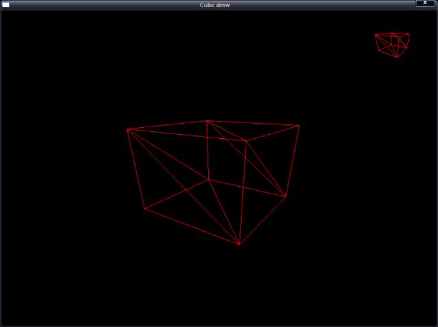
使用上下左右方向鍵來移動攝影機的位置。
運行效果: