|
現(xiàn)在是二月,而且到如今你或許已經(jīng)讀到、或聽(tīng)到人們談?wù)揢ML 2.0 —— 包括若干進(jìn)步的 UML 的新規(guī)范,所做的變化。考慮到新規(guī)范的重要性,我們也正在修改這個(gè)文章系列的基礎(chǔ),把我們的注意力從 OMG 的 UML 1.4 規(guī)范,轉(zhuǎn)移到 OMG 的已采納 UML 2.0草案規(guī)范(又名 UML 2)。我不喜歡在一系列文章的中間,把重點(diǎn)從 1.4 變?yōu)?2.0 ,但是 UML 2.0 草案規(guī)范是前進(jìn)的重要一步,我感覺(jué)需要擴(kuò)充文字。
由于一些理由,OMG 改良了 UML 。主要的理由是,他們希望 UML 模型能夠表達(dá)模型驅(qū)動(dòng)架構(gòu)(MDA),這意味著 UML 必須支持更多的模型驅(qū)動(dòng)的符號(hào)。同時(shí), UML 1.x 符號(hào)集合有時(shí)難以適用于較大的應(yīng)用程序。此外,為了要使圖變成更容易閱讀,需要改良符號(hào)元件。(舉例來(lái)說(shuō),UML 1.x 的模型邏輯流程太復(fù)雜,有時(shí)不可能完成。對(duì)UML 2 中的序列圖的符號(hào)集合的改變,已經(jīng)在序列化邏輯建模方面取得巨大的進(jìn)步)。
注意我上面所述的文字:“已采納UML2.0草案規(guī)范。”確實(shí),規(guī)范仍然處于草案狀態(tài),但是關(guān)鍵是草案規(guī)范已經(jīng)被 OMG 采用,OMG是一個(gè)直到新標(biāo)準(zhǔn)相當(dāng)可靠,才會(huì)采用它們的組織。 在 UML 2 完全地被采用之前,規(guī)范將會(huì)有一些修改,但是這些改變應(yīng)該是極小的。主要的改變將會(huì)是在 UML 的內(nèi)部 —— 包括通常被實(shí)施 UML 工具的軟件公司使用的功能。
本文的主要目的是繼續(xù)把我們的重點(diǎn)放在基礎(chǔ)UML圖上;這個(gè)月,我們進(jìn)一步了解序列圖。再次請(qǐng)注意,下面提供的例子正是以新的 UML 2 規(guī)范為基礎(chǔ)。
圖的目的
序列圖主要用于按照交互發(fā)生的一系列順序,顯示對(duì)象之間的這些交互。很象類圖,開(kāi)發(fā)者一般認(rèn)為序列圖只對(duì)他們有意義。然而,一個(gè)組織的業(yè)務(wù)人員會(huì)發(fā)現(xiàn),序列圖顯示不同的業(yè)務(wù)對(duì)象如何交互,對(duì)于交流當(dāng)前業(yè)務(wù)如何進(jìn)行很有用。除記錄組織的當(dāng)前事件外,一個(gè)業(yè)務(wù)級(jí)的序列圖能被當(dāng)作一個(gè)需求文件使用,為實(shí)現(xiàn)一個(gè)未來(lái)系統(tǒng)傳遞需求。在項(xiàng)目的需求階段,分析師能通過(guò)提供一個(gè)更加正式層次的表達(dá),把用例帶入下一層次。那種情況下,用例常常被細(xì)化為一個(gè)或者更多的序列圖。
組織的技術(shù)人員能發(fā)現(xiàn),序列圖在記錄一個(gè)未來(lái)系統(tǒng)的行為應(yīng)該如何表現(xiàn)中,非常有用。在設(shè)計(jì)階段,架構(gòu)師和開(kāi)發(fā)者能使用圖,挖掘出系統(tǒng)對(duì)象間的交互,這樣充實(shí)整個(gè)系統(tǒng)設(shè)計(jì)。
序列圖的主要用途之一,是把用例表達(dá)的需求,轉(zhuǎn)化為進(jìn)一步、更加正式層次的精細(xì)表達(dá)。用例常常被細(xì)化為一個(gè)或者更多的序列圖。序列圖除了在設(shè)計(jì)新系統(tǒng)方面的用途外,它們還能用來(lái)記錄一個(gè)存在系統(tǒng)(稱它為“遺產(chǎn)”)的對(duì)象現(xiàn)在如何交互。當(dāng)把這個(gè)系統(tǒng)移交給另一個(gè)人或組織時(shí),這個(gè)文檔很有用。
符號(hào)
既然這是我基于 UML 2的 UML 圖系列文章的第一篇,我們需要首先討論對(duì) UML 2 圖符號(hào)的一個(gè)補(bǔ)充,即一個(gè)叫做框架的符號(hào)元件。在 UML 2中,框架元件用于作為許多其他的圖元件的一個(gè)基礎(chǔ),但是大多數(shù)人第一次接觸框架元件的情況,是作為圖的圖形化邊界。當(dāng)為圖提供圖形化邊界時(shí),一個(gè)框架元件為圖的標(biāo)簽提供一致的位置。在 UML 圖中框架元件是可選擇的;就如你能在圖 1 和 2 中見(jiàn)到的,圖的標(biāo)簽被放在左上角,在我將調(diào)用框架的“namebox”中,一種卷角長(zhǎng)方形,而且實(shí)際的 UML 圖在較大的封閉長(zhǎng)方形內(nèi)部定義。
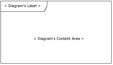
圖 1: 空的 UML 2 框架元件
除了提供一個(gè)圖形化邊框之外,用于圖中的框架元件也有描述交互的重要的功能, 例如序列圖。在序列圖上一個(gè)序列接收和發(fā)送消息(又稱交互),能通過(guò)連接消息和框架元件邊界,建立模型(如圖 2 所見(jiàn)到)。這將會(huì)在后面“超越基礎(chǔ)”的段落中被更詳細(xì)地介紹。
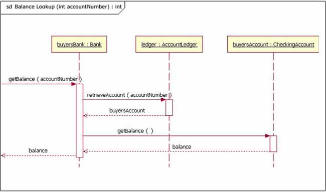
圖 2: 一個(gè)接收和發(fā)送消息的序列圖
注意在圖 2 中,對(duì)于序列圖,圖的標(biāo)簽由文字“sd”開(kāi)始。當(dāng)使用一個(gè)框架元件封閉一個(gè)圖時(shí),圖的標(biāo)簽需要按照以下的格式:
UML 規(guī)范給圖類型提供特定的文本值。(舉例來(lái)說(shuō),sd代表序列圖,activity代表活動(dòng)圖,use case代表用例圖)。
基礎(chǔ)
序列圖的主要目的是定義事件序列,產(chǎn)生一些希望的輸出。重點(diǎn)不是消息本身,而是消息產(chǎn)生的順序;不過(guò),大多數(shù)序列圖會(huì)表示一個(gè)系統(tǒng)的對(duì)象之間傳遞的什么消息,以及它們發(fā)生的順序。圖按照水平和垂直的維度傳遞信息:垂直維度從上而下表示消息/調(diào)用發(fā)生的時(shí)間序列,而且水平維度從左到右表示消息發(fā)送到的對(duì)象實(shí)例。
生命線
當(dāng)畫(huà)一個(gè)序列圖的時(shí)候,放置生命線符號(hào)元件,橫跨圖的頂部。生命線表示序列中,建模的角色或?qū)ο髮?shí)例。 1 生命線畫(huà)作一個(gè)方格,一條虛線從上而下,通過(guò)底部邊界的中心(圖 3)。生命線名字放置在方格里。
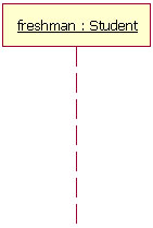
圖 3: 用于一個(gè)實(shí)體名為freshman的生命線的Student類的一個(gè)例子
UML 的生命線命名標(biāo)準(zhǔn)按照如下格式:
在如圖3所示的例子中,生命線表示類Student的實(shí)體,它的實(shí)體名稱是freshman。這里注意一點(diǎn),生命線名稱帶下劃線。當(dāng)使用下劃線時(shí),意味著序列圖中的生命線代表一個(gè)類的特定實(shí)體,不是特定種類的實(shí)體(例如,角色)。在將來(lái)的一篇文章中,我們將會(huì)了解結(jié)構(gòu)化建模。現(xiàn)在,僅僅評(píng)述序列圖,可能包含角色(例如買方和賣方),而不需要敘述誰(shuí)扮演那些角色(例如Bill和Fred)。這準(zhǔn)許不同語(yǔ)境的圖重復(fù)使用。簡(jiǎn)單拖放,序列圖的實(shí)例名稱有下劃線,而角色名稱沒(méi)有。
圖 3 中我們生命線例子是一個(gè)命名的對(duì)象,但是不是所有的生命線都代表命名的對(duì)象。相反的,一個(gè)生命線能用來(lái)表現(xiàn)一個(gè)匿名的或未命名的實(shí)體。當(dāng)在一個(gè)序列圖上,為一個(gè)未命名的實(shí)例建模時(shí),生命線的名字采用和一個(gè)命名實(shí)例相同的模式;但是生命線名字的位置留下空白,而不是提供一個(gè)例圖名字。再次參考圖 3,如果生命線正在表現(xiàn)Student類的一個(gè)匿名例圖,生命線會(huì)是: “Student”。同時(shí), 因?yàn)樾蛄袌D在項(xiàng)目設(shè)計(jì)階段中使用,有一個(gè)未指定的對(duì)象是完全合法: 舉例來(lái)說(shuō),“freshman”。
消息
為了可讀性,序列圖的第一個(gè)消息總是從頂端開(kāi)始,并且一般位于圖的左邊。然后繼發(fā)的消息加入圖中,稍微比前面的消息低些。
為了顯示一個(gè)對(duì)象(例如,生命線)傳遞一個(gè)消息給另外一個(gè)對(duì)象,你畫(huà)一條線指向接收對(duì)象,包括一個(gè)實(shí)心箭頭(如果是一個(gè)同步調(diào)用操作)或一個(gè)棍形箭頭(如果是一個(gè)異步訊號(hào))。消息/方法名字放置在帶箭頭的線上面。正在被傳遞給接收對(duì)象的消息,表示接收對(duì)象的類實(shí)現(xiàn)的一個(gè)操作/方法。在圖 4 的例子中,analyst對(duì)象調(diào)用ReportingSystem 類的一個(gè)實(shí)例的系統(tǒng)對(duì)象。analyst對(duì)象在調(diào)用系統(tǒng)對(duì)象的 getAvailableReports 方法。系統(tǒng)對(duì)象然后調(diào)用secSystem 對(duì)象上的、包括參數(shù)userId的getSecurityClearance 方法,secSystem的類的類型是 SecuritySystem。 2
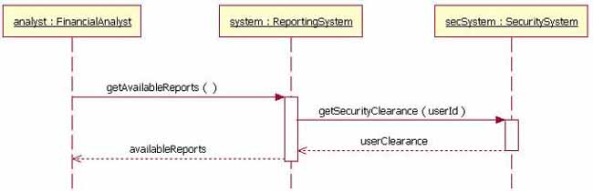
圖 4: 一個(gè)在對(duì)象之間傳遞消息的實(shí)例
除了僅僅顯示序列圖上的消息調(diào)用外,圖 4 中的圖還包括返回消息。這些返回消息是可選擇的;一個(gè)返回消息畫(huà)作一個(gè)帶開(kāi)放箭頭的虛線,向后指向來(lái)源的生命線,在這條虛線上面,你放置操作的返回值。在圖 4 中,當(dāng) getSecurityClearance 方法被調(diào)用時(shí),secSystem 對(duì)象返回 userClearance 給系統(tǒng)對(duì)象。當(dāng) getAvailableReports 方法被調(diào)用時(shí),系統(tǒng)對(duì)象返回 availableReports。
此外,返回消息是序列圖的一個(gè)可選擇部分。返回消息的使用依賴建模的具體/抽象程度。如果需要較好的具體化,返回消息是有用的;否則,主動(dòng)消息就足夠了。我個(gè)人喜歡,無(wú)論什么時(shí)候返回一個(gè)值,都包括一個(gè)返回消息,因?yàn)槲野l(fā)現(xiàn)額外的細(xì)節(jié)使一個(gè)序列圖變得更容易閱讀。
當(dāng)序列圖建模時(shí),有時(shí)候,一個(gè)對(duì)象將會(huì)需要傳遞一個(gè)消息給它本身。一個(gè)對(duì)象何時(shí)稱它本身?一個(gè)純化論者會(huì)爭(zhēng)辯一個(gè)對(duì)象應(yīng)該永不傳遞一個(gè)消息給它本身。然而,為傳遞一個(gè)消息給它本身的對(duì)象建模,在一些情境中可能是有用的。舉例來(lái)說(shuō),圖 5 是圖 4 的一個(gè)改良版本。 圖 5 版本顯示調(diào)用它的 determineAvailableReports 方法的系統(tǒng)對(duì)象。通過(guò)表示系統(tǒng)傳遞消息“determineAvailableReports”給它本身,模型把注意力集中到過(guò)程的事實(shí)上,而不是系統(tǒng)對(duì)象。
為了要畫(huà)一個(gè)調(diào)用本身的對(duì)象,如你平時(shí)所作的,畫(huà)一條消息,但是不是連接它到另外的一個(gè)對(duì)象,而是你把消息連接回對(duì)象本身。
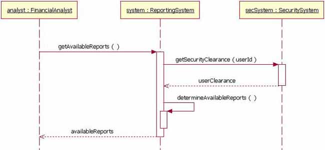
圖 5: 系統(tǒng)對(duì)象調(diào)用它的 determineAvailableReports 方法
圖 5 中的消息實(shí)例顯示同步消息;然而,在序列圖中,你也能為異步消息建模。一個(gè)異步消息和一個(gè)同步的畫(huà)法類似,但是消息畫(huà)的線帶一個(gè)棍形矛頭,如圖 6 所示。
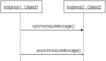
圖 6: 表示傳遞到實(shí)體2的異步消息的序列圖片段
約束
當(dāng)為對(duì)象的交互建模時(shí),有時(shí)候,必須滿足一個(gè)條件,消息才會(huì)傳遞給對(duì)象。約束在 UML 圖各處中,用于控制流。在這里,我將會(huì)討論UML 1.x 及UML 2.0兩者的約束。在 UML 1.x 中,一個(gè)約束只可能被分配到一個(gè)單一消息。UML 1.x中,為了在一個(gè)序列圖上畫(huà)一個(gè)約束,你把約束元件放在約束的消息線上,消息名字之前。圖 7 顯示序列圖的一個(gè)片段,消息addStudent 方法上有一個(gè)約束。
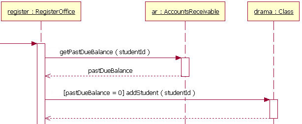
圖 7:UML 1.x 序列圖的一個(gè)片段,其中addStudent 消息有一個(gè)約束
在圖 7 中,約束是文本“[ pastDueBalance=0]”。通過(guò)這個(gè)消息上的約束,如果應(yīng)收帳系統(tǒng)返回一個(gè)零點(diǎn)的逾期平衡,addStudent 消息才將會(huì)被傳遞。約束的符號(hào)很簡(jiǎn)單;格式是:
舉例來(lái)說(shuō),
組合碎片(變體方案,選擇項(xiàng),和循環(huán))
然而,在大多數(shù)的序列圖中,UML 1.x“in-line”約束不足以處理一個(gè)建模序列的必需邏輯。這個(gè)功能缺失是 UML 1.x 的一個(gè)問(wèn)題。UML 2 已經(jīng)通過(guò)去掉“in-line”約束,增加一個(gè)叫做組合碎片的符號(hào)元件,解決了這一個(gè)問(wèn)題。一個(gè)組合碎片用來(lái)把一套消息組合在一起,在一個(gè)序列圖中顯示條件分支。UML 2 規(guī)范指明了組合碎片的 11 種交互類型。十一種中的三種將會(huì)在“基礎(chǔ)”段落中介紹,另外兩種類型將會(huì)在“超越基礎(chǔ)”中介紹,而那剩余的六種我將會(huì)留在另一篇文章中介紹。(嗨,這是一篇文章而不是一本書(shū)。我希望你在一天中看完這部分!)
變體
變體用來(lái)指明在兩個(gè)或更多的消息序列之間的、互斥的選擇。 3 變體支持經(jīng)典的“if then else”邏輯的建模(舉例來(lái)說(shuō),如果 我買三個(gè),然后 我得到 我購(gòu)買的20% 折扣;否則 我得到我購(gòu)買的 10% 折扣)。
就如你將會(huì)在圖 8 中注意到的,一個(gè)變體的組合碎片元件使用框架來(lái)畫(huà)。單詞“alt”放置在框架的namebox里。然后較大的長(zhǎng)方形分為 UML 2 所稱的操作元。 4 操作元被虛線分開(kāi)。每個(gè)操作元有一個(gè)約束進(jìn)行測(cè)試,而這個(gè)約束被放置在生命線頂端的操作元的左上部。 5 如果操作元的約束等于“true”,然后那個(gè)操作元是要執(zhí)行的操作元。
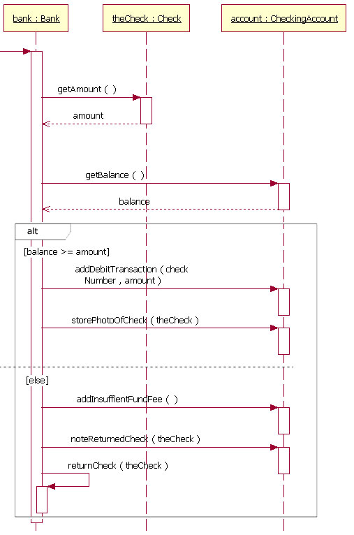
圖 8:包含變體組合碎片的一個(gè)序列圖片段
圖 8作為一個(gè)變體的組合碎片如何閱讀的例子,顯示序列從頂部開(kāi)始,即bank對(duì)象獲取支票金額和帳戶結(jié)余。此時(shí),序列圖中的變體組合碎片接管。因?yàn)榧s束“[balance >= amount]”,如果余額超過(guò)或等于金額,然后順序進(jìn)行bank對(duì)象傳遞 addDebitTransaction 和 storePhotoOfCheck 消息給account對(duì)象。然而,如果余額不是超過(guò)或等于金額,然后順序的過(guò)程就是bank傳遞addInsuffientFundFee 和 noteReturnedCheck 消息給account對(duì)象,returnCheck 消息給它自身。因?yàn)?#8220;else”約束,當(dāng)余額不大于或者等于金額時(shí),第二個(gè)序列被調(diào)用。在變體的組合碎片中,不需要“else”約束;而如果一個(gè)操作元,在它上面沒(méi)有一個(gè)明確的約束,那么將假定“else”約束。
變體的組合碎片沒(méi)被限制在簡(jiǎn)單的“if then else”驗(yàn)證。可能需要大量的變體路徑。 如果需要較多的變體方案,你一定要做的全部工作就是把一個(gè)操作元加入有序列約束和消息的長(zhǎng)方形中。
選擇項(xiàng)
選擇項(xiàng)組合碎片用來(lái)為序列建模,這些序列給予一個(gè)特定條件,將會(huì)發(fā)生的;或者,序列不發(fā)生。一個(gè)選擇項(xiàng)用來(lái)為簡(jiǎn)單的“if then”表達(dá)式建模。(例如,如果架上的圈餅少于五個(gè),那么另外做兩打圈餅)。
選擇項(xiàng)組合碎片符號(hào)與變體組合碎片類似,除了它只有一個(gè)操作元并且永不能有“else”約束以外(它就是如此,沒(méi)有理由)。要畫(huà)選擇項(xiàng)組合,你畫(huà)一個(gè)框架。文字“opt”是被放置在框架的 namebox 里的文本,在框架的內(nèi)容區(qū),選擇項(xiàng)的約束被放置在生命線頂端上的左上角。 然后選擇項(xiàng)的消息序列被放在框架的內(nèi)容區(qū)的其余位置內(nèi)。這些元件如圖 9 所示。
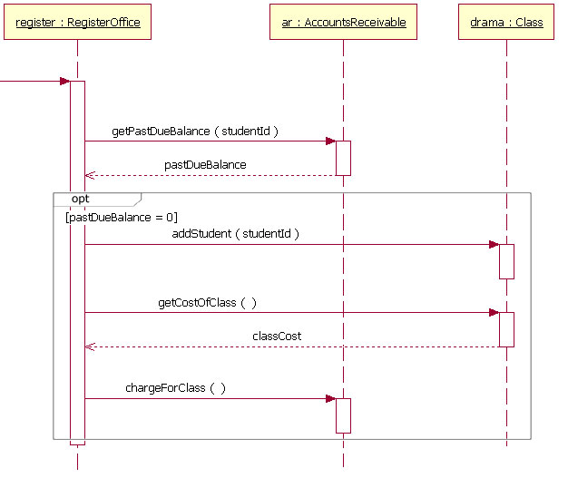
圖 9:包括選擇項(xiàng)組合碎片的一個(gè)序列圖片段
閱讀選擇項(xiàng)組合碎片很容易。圖 9 是圖 7 的序列圖片段的再加工,但是這次它使用一個(gè)選擇項(xiàng)組合碎片,因?yàn)槿绻鸖tudent的逾期平衡等于0,需要傳遞更多的消息。按照?qǐng)D 9 的序列圖,如果Student的逾期平衡等于零,然后傳遞addStudent,getCostOfClass和chargeForClass消息。如果Student的逾期平衡不等于零,那么在選擇項(xiàng)組合碎片中,序列不傳遞任何一個(gè)消息。
例子圖 9的序列圖片段包括一個(gè)選擇項(xiàng)約束;然而,約束不是一個(gè)必需的元件。在高層次、抽象的序列圖中,你可能不想敘述選擇項(xiàng)的條件。你可能只是想要指出片段是可選擇的。
循環(huán)
有時(shí)候你將會(huì)需要為一個(gè)重復(fù)的序列建模。在 UML 2 中,為一個(gè)重復(fù)的序列建模已經(jīng)改良,附加了循環(huán)組合碎片。
循環(huán)組合碎片表面非常類似選擇項(xiàng)組合碎片。你畫(huà)一個(gè)框架,在框架的 namebox 中放置文本“loop”。在框架的內(nèi)容區(qū)中,一個(gè)生命線的頂部,循環(huán)約束 6 被放置在左上角。然后循環(huán)的消息序列被放在框架內(nèi)容區(qū)的其余部分中。在一個(gè)循環(huán)中,除了標(biāo)準(zhǔn)的布爾測(cè)試外,一個(gè)約束能測(cè)試二個(gè)特定的條件式。特定的約束條件式是寫(xiě)作“minint = [the number]”(例如,“minint = 1”)的最小循環(huán)次數(shù),和寫(xiě)作“maxint = [the number]”(例如,“maxint = 5”)的最大循環(huán)次數(shù)。通過(guò)最小循環(huán)檢驗(yàn),循環(huán)必須運(yùn)行至少指定次數(shù),而循環(huán)執(zhí)行次數(shù)不能達(dá)到約束指定的最大循環(huán)次數(shù)。
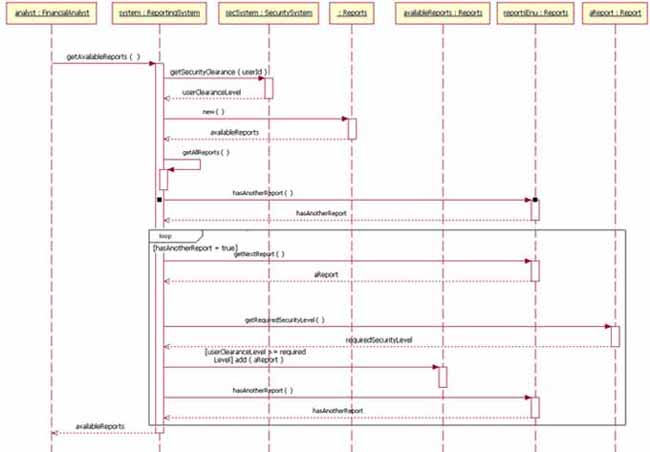
圖 10:循環(huán)組合碎片的一個(gè)序列圖例子 (單擊放大)
在圖 10 中顯示的循環(huán)運(yùn)行,直到 reportsEnu 對(duì)象的 hasAnotherReport 消息返回false。如果循環(huán)序列應(yīng)該運(yùn)行,這個(gè)序列圖的循環(huán)使用一個(gè)布爾測(cè)試確認(rèn)。為了閱讀這個(gè)圖,你和平常一樣,從頂部開(kāi)始。當(dāng)你到達(dá)循環(huán)組合碎片,做一個(gè)測(cè)試,看看值 hasAnotherReport 是否等于true。如果 hasAnotherReport 值等于true,于是序列進(jìn)入循環(huán)片斷。然后你能和正常情況一樣,在序列圖中跟蹤循環(huán)的消息。
超越基礎(chǔ)
我已經(jīng)介紹了序列圖的基礎(chǔ),應(yīng)該使你可以為將會(huì)在系統(tǒng)中通常發(fā)生的大部份交互建模。下面段落將會(huì)介紹用于序列圖的比較高階的符號(hào)元件。
引用另外一個(gè)序列圖
當(dāng)做序列圖的時(shí)候,開(kāi)發(fā)者愛(ài)在他們的序列圖中,重用存在的序列圖。 7 在 UML 2 中開(kāi)始,引進(jìn)“交互進(jìn)行”元件。追加交互進(jìn)行的可以說(shuō)是 UML 2 交互建模中的最重要的創(chuàng)新。交互進(jìn)行增加了功能,把原始的序列圖組織成為復(fù)雜的序列圖。由于這些,你能組合(重用)較簡(jiǎn)單的序列,生成比較復(fù)雜的序列。這意味你能把完整的、可能比較復(fù)雜的序列,抽象為一個(gè)單一的概念單位。
一個(gè)交互進(jìn)行元件使用一個(gè)框架繪制。文字“ref”放置在框架的 namebox 中,引用的序列圖名字放置在框架的內(nèi)容區(qū)里,連同序列圖的任何參數(shù)一起。引用序列圖的名字符號(hào)如下模式:
兩個(gè)例子:
1. Retrieve Borrower Credit Report(ssn) : borrowerCreditReport
或者
2. Process Credit Card(name, number, expirationDate, amount : 100)
在例子 1 中,語(yǔ)法調(diào)用叫做Retrieve Borrower Credit Report的序列圖,傳遞給它參數(shù) ssn。序列Retreive Borrower Credit Report返回變量 borrowerCreditReport 。
在實(shí)例 2 中,語(yǔ)法調(diào)用叫做Process Credit Card的序列圖,傳遞給它參數(shù)name,number,expiration date,和 amount。然而,在例子 2 中,amount參數(shù)將會(huì)是值100。因?yàn)槔?沒(méi)有返回值標(biāo)簽,序列不返回值(假設(shè),建模的序列不需要返回值)。
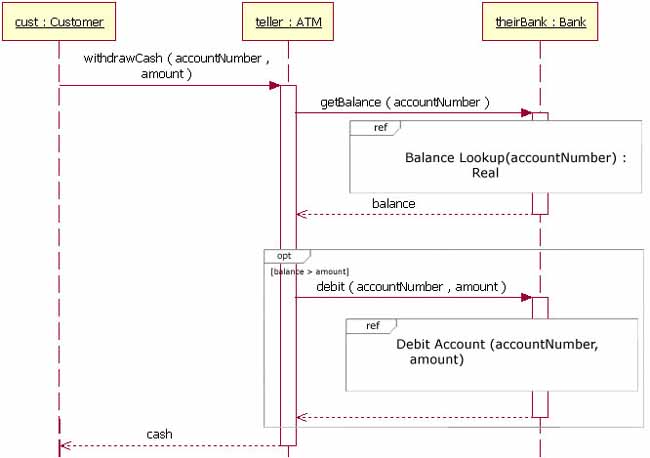
圖 11: 一個(gè)引用兩個(gè)不同序列圖的序列圖
圖 11 顯示一個(gè)序列圖,它引用了序列圖“Balance Lookup”和“Debit Account”。序列從左上角開(kāi)始,客戶傳遞一個(gè)消息給teller對(duì)象。teller對(duì)象傳遞一個(gè)消息給 theirBank 對(duì)象。那時(shí),調(diào)用Balance Lookup序列圖,而 accountNumber作為一個(gè)參數(shù)傳遞。Balance Lookup序列圖返回balance變量。然后檢驗(yàn)選擇項(xiàng)組合碎片的約束條件,確認(rèn)余額大于金額變量。在余額比金額更大的情況下,調(diào)用Debit Account序列圖,給它傳遞參數(shù)accountNumber 和amount。在那個(gè)序列完成后,withdrawCash 消息為客戶返回cash。
重要的是,注意在圖 11 中,theirBank 的生命線被交互進(jìn)行Balance Lookup隱藏了。因?yàn)榻换ミM(jìn)行隱藏生命線,意味著theirBank 生命線在“Balance Lookup”序列圖中被引用。除了隱藏交互進(jìn)行的生命線之外,UML 2 也指明,生命線在它自己的“Balance Lookup”序列中,一定有相同的 theirBank 。
有時(shí)候,你為一個(gè)序列圖建模,其中交互進(jìn)行會(huì)重疊沒(méi)有 在交互進(jìn)行中引用的生命線。在那種情況下,生命線和正常的生命線一樣顯示,不會(huì)被重疊的交互進(jìn)行隱藏。
在圖 11 中,序列引用“Balance Lookup”序列圖。“Balance Lookup”序列圖在圖 12 中顯示。因?yàn)槔有蛄杏袇?shù)和一個(gè)返回值,它的標(biāo)簽 —— 位于圖的 namebox 中 —— 按照一個(gè)特定模式:
圖類型 圖名 [參數(shù)類型:參數(shù)名]
|
兩個(gè)例子:
1. SD Balance Lookup(Integer : accountNumber) : Real
或
2. SD Available Reports(Financial Analyst : analyst) : Reports
圖 12 舉例說(shuō)明例子 1,在里面,Balance Lookup序列把參數(shù) accountNumber 作為序列中的變量使用,序列圖顯示返回的Real對(duì)象。在類似這種情況下,返回的對(duì)象采用序列圖實(shí)體名。
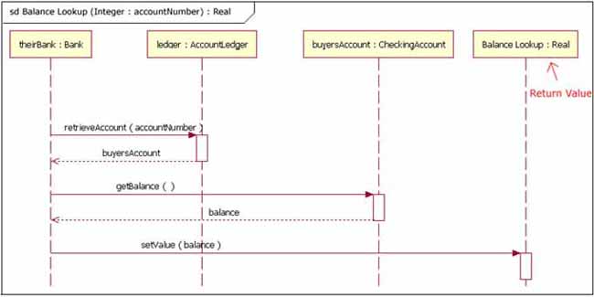
圖 12: 一個(gè)使用 accountNumber 參數(shù)并返回一個(gè)Real對(duì)象的序列圖
圖 13 舉例說(shuō)明例子 2,在里面,一個(gè)序列圖獲取一個(gè)參數(shù),返回一個(gè)對(duì)象。然而,在圖 13 中參數(shù)在序列的交互中使用。
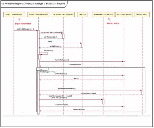
圖 13: 一個(gè)在它的交互中使用參數(shù)、返回一個(gè)Reports對(duì)象的序列圖
門
前面的段落展示如何通過(guò)參數(shù)和返回值傳遞信息,引用另一個(gè)序列圖。然而,有另一個(gè)方法在序列圖之間傳遞消息。門可能是一個(gè)容易的方法,為在序列圖和它的上下文之間的傳遞消息建模。一個(gè)門只是一個(gè)消息,圖形表示為一端連接序列圖的框架邊緣,另一端連接到生命線。使用門的圖 11 和 12 ,在圖 14 和 15 中可以被看到重構(gòu)。圖 15 的例圖有一個(gè)叫做getBalance的入口門,獲取參數(shù) accountNumber。因?yàn)槭羌^的線連接到圖的框架,而箭頭連接到生命線,所以 getBalance 消息是一個(gè)入口門。序列圖也有一個(gè)出囗門,返回balance變量。出口門同理可知,因?yàn)樗且粋€(gè)返回消息,連接從一個(gè)生命線到圖的框架,箭頭連接框架。
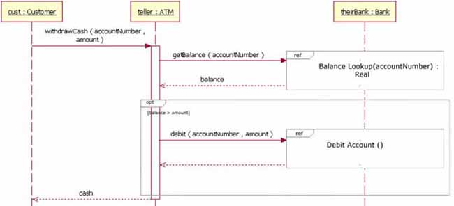
圖 14: 圖 11 的重構(gòu),這次使用門
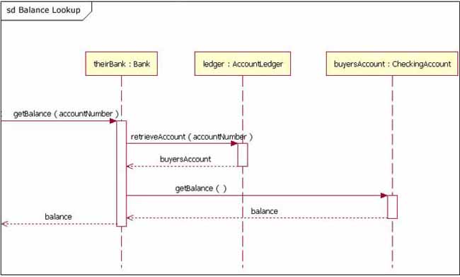
圖 15: 圖 12 的重構(gòu),這次使用門
組合碎片(跳轉(zhuǎn)和并行)
在本文前面“基礎(chǔ)”的段落中呈現(xiàn)的,我介紹了“變體”,“選擇項(xiàng)”,和“循環(huán)”的組合碎片。這些三個(gè)組合碎片是大多數(shù)人將會(huì)使用最多的。然而,有二個(gè)其他的組合碎片,大量共享的人將會(huì)發(fā)現(xiàn)有用——跳轉(zhuǎn)和并行。
跳轉(zhuǎn)
跳轉(zhuǎn)組合碎片幾乎在每個(gè)方面都和選擇項(xiàng)組合碎片一致,除了兩個(gè)例外。首先,跳轉(zhuǎn)的框架namebox的文本“break”代替了“option”。其次, 當(dāng)一個(gè)跳轉(zhuǎn)組合碎片的消息運(yùn)行時(shí),封閉的交互作用的其他消息將不會(huì)執(zhí)行,因?yàn)樾蛄写蚱屏朔忾]的交互。這樣,跳轉(zhuǎn)組合碎片非常象 C++ 或 Java 的編程語(yǔ)言中的break關(guān)鍵字。
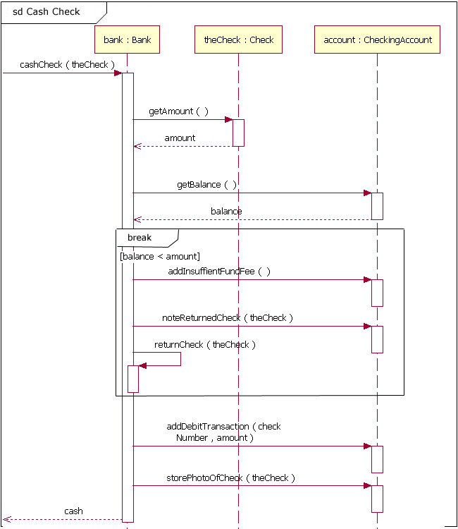
圖 16: 來(lái)自圖 8 的序列圖片段的重構(gòu),片段使用跳轉(zhuǎn)代替變體
跳轉(zhuǎn)最常用來(lái)做模型異常處理。圖 16 是圖 8 的重構(gòu),但是這次圖16使用跳轉(zhuǎn)組合碎片,因?yàn)樗裝alance < amount的情況作為一個(gè)異常對(duì)待,而不是一個(gè)變體流。要閱讀圖 16,你從序列的左上角開(kāi)始,向下讀。當(dāng)序列到達(dá)返回值“balance”的時(shí)候,它檢查看看是否余額比金額更少。如果余額不少于金額,被傳遞的下一個(gè)消息是 addDebitTransaction 消息,而且序列正常繼續(xù)。然而,在余額比金額更少的情況下,然后序列進(jìn)入跳轉(zhuǎn)組合碎片,它的消息被傳遞。一旦跳轉(zhuǎn)組合的消息的已經(jīng)被傳遞,序列不發(fā)送任何其它消息就退出(舉例來(lái)說(shuō),addDebitTransaction)。
注意有關(guān)跳轉(zhuǎn)的一件重要的事是,它們只引起一個(gè)封閉交互的序列退出,不必完成圖中描述的序列。在這種情況下,跳轉(zhuǎn)組合是變體或者循環(huán)的一部分,然后只是變體或循環(huán)被退出。
并行
今天的現(xiàn)代計(jì)算機(jī)系統(tǒng)在復(fù)雜性和有時(shí)執(zhí)行并發(fā)任務(wù)方面不斷進(jìn)步。當(dāng)完成一個(gè)復(fù)雜任務(wù)需要的處理時(shí)間比希望的長(zhǎng)的時(shí)候,一些系統(tǒng)采用并行處理進(jìn)程的各部分。當(dāng)創(chuàng)造一個(gè)序列圖,顯示并行處理活動(dòng)的時(shí)候,需要使用并行組合碎片元件。
并行組合碎片使用一個(gè)框架來(lái)畫(huà),你把文本“par”放在框架的 namebox 中。然后你把框架的內(nèi)容段用虛線分為水平操作元。框架的每個(gè)操作元表示一個(gè)在并行運(yùn)行的線程。
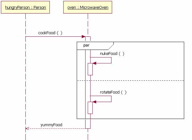
圖 17: oven 是并行做兩個(gè)任務(wù)的對(duì)象實(shí)例
圖 17 可能沒(méi)有舉例說(shuō)明做并行活動(dòng)的對(duì)象的最好的計(jì)算機(jī)系統(tǒng)實(shí)例,不過(guò)提供了一個(gè)容易理解的并行活動(dòng)序列的例子。序列如這樣進(jìn)行:hungryPerson 傳遞 cookFood 消息給oven 對(duì)象。當(dāng)oven 對(duì)象接收那個(gè)消息時(shí),它同時(shí)發(fā)送兩個(gè)消息(nukeFood 和 rotateFood)給它本身。這些消息都處理后,hungryPerson 對(duì)象從oven 對(duì)象返回 yummyFood 。
總結(jié)
序列圖是一個(gè)用來(lái)記錄系統(tǒng)需求,和整理系統(tǒng)設(shè)計(jì)的好圖。序列圖是如此好用的理由是,因?yàn)樗凑战换グl(fā)生的時(shí)間順序,顯示了系統(tǒng)中對(duì)象間的交互邏輯。
參考
- UML 2.0 Superstructure Final Adopted Specification (第8章部分) http://www.omg.org/cgi-bin/doc?ptc/2003-08-02
- UML 2 Sequence Diagram Overview http://www.agilemodeling.com/artifacts/sequenceDiagram.htm
- UML 2 Tutorial http://www.omg.org/news/meetings/workshops/UML%202003%20Manual/Tutorial7-Hogg.pdf
腳注
1 在完全建模系統(tǒng)中,對(duì)象(類的實(shí)例)也將會(huì)在系統(tǒng)的類圖中建模。
2 當(dāng)閱讀這個(gè)序列圖時(shí),假定分析師登錄進(jìn)入系統(tǒng)之內(nèi)。
3 請(qǐng)注意,附著在不同的變體操作元上的、兩個(gè)或更多的約束條件式的確可能同時(shí)是真,但是實(shí)際最多只有一個(gè)操作元將會(huì)在運(yùn)行時(shí)發(fā)生(那種情況下變體的“wins”沒(méi)有按照 UML 標(biāo)準(zhǔn)定義)。
4 雖然操作元看起來(lái)非常象公路上的小路,但是我特別不叫它們小路。泳道是在活動(dòng)圖上使用的 UML 符號(hào)。請(qǐng)參考The Rational Edge 早期關(guān)于 活動(dòng)圖的文章。
5 通常,附上約束的生命線是擁有包含在約束表達(dá)式中的變量的生命線。
6 關(guān)于選擇項(xiàng)組合碎片,循環(huán)組合碎片不需要在它上放置一個(gè)約束條件。
7 可能重用任何類型的序列圖(舉例來(lái)說(shuō),程序或業(yè)務(wù))。我只是發(fā)現(xiàn)開(kāi)發(fā)者更喜歡按功能分解他們的圖。
參考資料
- 您可以參閱本文在 developerWorks 全球站點(diǎn)上的 英文原文。
關(guān)于作者
 Donald Bell是IBM全球服務(wù)的一個(gè)IT專家,在那兒他和IBM的客戶一起致力于設(shè)計(jì)和開(kāi)發(fā)基于軟件解決方案的J2EE。 Donald Bell是IBM全球服務(wù)的一個(gè)IT專家,在那兒他和IBM的客戶一起致力于設(shè)計(jì)和開(kāi)發(fā)基于軟件解決方案的J2EE。 |
|