Soft-Edged Shadows
by Anirudh.S Shastry
ADVERTISEMENT
 <a target="_blank">
<img src="http://m1.2mdn.net/1001314/flip_300.gif" border="0" />
</a>
<a target="_blank">
<img src="http://m1.2mdn.net/1001314/flip_300.gif" border="0" />
</a>


|
Introduction
Originally, dynamic shadowing techniques were possible only in a limited way. But with the advent of powerful programmable graphicshardware, dynamic shadow techniques have nearly completely replaced static techniques like light mapping and semi-dynamic techniques like projected shadows. Two popular dynamic shadowing techniques are shadow volumes and shadow mapping.
A closer look
The shadow volumes technique is a geometry based technique that requires the extrusion of the geometry in the direction of the light to generate a closed volume. Then, via ray casting, the shadowed portions of the scene can be determined (usually the stencil buffer is used to simulate ray-casting). This technique is pixel-accurate and doesn't suffer from any aliasing problems, but as with any technique, it suffers from its share of disadvantages. Two major problems with this technique are that it is heavily geometry dependent and fill-rate intensive. Because of this, shadow mapping is slowly becoming more popular.
Shadow mapping on the other hand is an image space technique that involves rendering the scene depth from the light's point of view and using this depth information to determine which portions of the scene in shadow. Though this technique has several advantages, it suffers from aliasing artifacts and z-fighting. But there are solutions to this and since the advantages outweigh the disadvantages, this will be the technique of my choice in this article.
Soft shadows
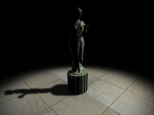
Hard shadows destroy the realism of a scene. Hence, we need to fake soft shadows in order to improve the visual quality of the scene. A lot of over-zealous PHD students have come up with papers describing soft shadowing techniques, but in reality, most of these techniques are not viable in real-time, at least when considering complex scenes. Until we have hardware that can overcome some of the limitations of these techniques, we will need to stick to more down-to-earth methods.
In this article, I present an image space method to generate soft-edged shadows using shadow maps. This method doesn't generate perfectly soft shadows (no umbra-penumbra). But it not only solves the aliasing problems of shadow mapping, it improves the visual quality by achieving aesthetically pleasing soft edged shadows.
So how does it work?
First, we generate the shadow map as usual by rendering the scene depth from the light's point of view into a floating point buffer. Then, instead of rendering the scene with shadows, we render the shadowed regions into a screen-sized buffer. Now, we can blur this using a bloom filter and project it back onto the scene in screen space. Sounds simple right?
In this article, we only deal with spot lights, but this technique can easily be extended to handle point lights as well.
Here are the steps:
- Generate the shadow map as usual by writing the scene depth into a floating point buffer.
- Render the shadowed portions of the scene after depth comparison into fixed point texture, without any lighting.
- Blur the above buffer using a bloom filter (though we use a separable Gaussian filter in this article, any filter can be used).
- Project the blurred buffer onto the scene in screen space to get cool soft-edged shadows, along with full lighting.
Step 1: Rendering the shadow map
First, we need to create a texture that can hold the scene depth. Since we need to use this as a render target, we will also need to create a surface that holds the texture's surface data. The texture must be a floating point one because of the large range of depth values. The R32F format has sufficient precision and so we use it. Here's the codelet that is used to create the texture.
if( FAILED( g_pd3dDevice->CreateTexture( SHADOW_MAP_SIZE, SHADOW_MAP_SIZE, 1,
D3DUSAGE_RENDERTARGET, D3DFMT_R32F,
D3DPOOL_DEFAULT, &g_pShadowMap,
NULL ) ) )
{
MessageBox( g_hWnd, "Unable to create shadow map!",
"Error", MB_OK | MB_ICONERROR );
return E_FAIL;
}
g_pShadowMap->GetSurfaceLevel( 0, &g_pShadowSurf );
Now, to generate the shadow map, we need to render the scene's depth to the shadow map. To do this, we must render the scene with the light's world-view-projection matrix. Here's how we build that matrix.
D3DXMatrixLookAtLH( &matView, &vLightPos, &vLightAim, &g_vUp );
D3DXMatrixPerspectiveFovLH( &matProj, D3DXToRadian(30.0f), 1.0f, 1.0f, 1024.0f );
matLightViewProj = matWorld * matView * matProj;
Here are vertex and pixel shaders for rendering the scene depth.
struct VSOUTPUT_SHADOW
{
float4 vPosition : POSITION;
float fDepth : TEXCOORD0;
};
VSOUTPUT_SHADOW VS_Shadow( float4 inPosition : POSITION )
{
VSOUTPUT_SHADOW OUT = (VSOUTPUT_SHADOW)0;
OUT.vPosition = mul( inPosition, g_matLightViewProj );
OUT.fDepth = OUT.vPosition.z;
return OUT;
}
Here, we multiply the position by the light's world-view-projection matrix (g_matLightViewProj) and use the transformed position's z-value as the depth. In the pixel shader, we output the depth as the color.
float4 PS_Shadow( VSOUTPUT_SHADOW IN ) : COLOR0
{
return float4( IN.fDepth, IN.fDepth, IN.fDepth, 1.0f );
}
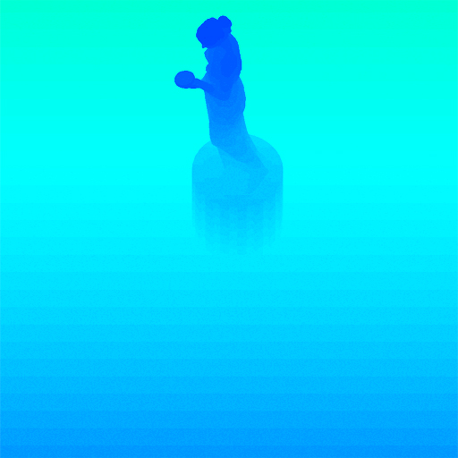
Voila! We have the shadow map. Below is a color coded version of the shadow map, dark blue indicates smaller depth values, whereas light blue indicates larger depth values.
Step 2: Rendering the shadowed scene into a buffer
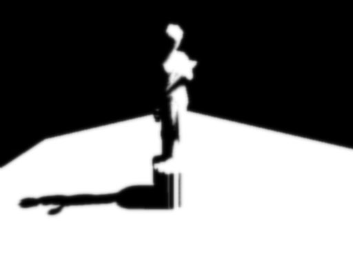
Next, we need to render the shadowed portions of the scene to an offscreen buffer so that we can blur it and project it back onto the scene. To do that, we first render the shadowed portions of the scene into a screen-sized fixed point texture.
if( FAILED( g_pd3dDevice->CreateTexture( SCREEN_WIDTH, SCREEN_HEIGHT, 1,
D3DUSAGE_RENDERTARGET, D3DFMT_A8R8G8B8, D3DPOOL_DEFAULT, &g_pScreenMap, NULL ) ) )
{
MessageBox( g_hWnd, "Unable to create screen map!",
"Error", MB_OK | MB_ICONERROR );
return E_FAIL;
}
g_pScreenMap->GetSurfaceLevel( 0, & g_pScreenSurf );
To get the projective texture coordinates, we need a "texture" matrix that will map the position from projection space to texture space.
float fTexOffs = 0.5 + (0.5 / (float)SHADOW_MAP_SIZE);
D3DXMATRIX matTexAdj( 0.5f, 0.0f, 0.0f, 0.0f,
0.0f, -0.5f, 0.0f, 0.0f,
0.0f, 0.0f, 1.0f, 0.0f,
fTexOffs, fTexOffs, 0.0f, 1.0f );
matTexture = matLightViewProj * matTexAdj;
We get the shadow factor as usual by depth comparison, but instead of outputting the completely lit scene, we output only the shadow factor. Here are the vertex and pixel shaders that do the job.
struct VSOUTPUT_UNLIT
{
float4 vPosition : POSITION;
float4 vTexCoord : TEXCOORD0;
float fDepth : TEXCOORD1;
};
VSOUTPUT_UNLIT VS_Unlit( float4 inPosition : POSITION )
{
VSOUTPUT_UNLIT OUT = (VSOUTPUT_UNLIT)0;
OUT.vPosition = mul( inPosition, g_matWorldViewProj );
OUT.vTexCoord = mul( inPosition, g_matTexture );
OUT.fDepth = mul( inPosition, g_matLightViewProj ).z;
return OUT;
}
We use percentage closer filtering (PCF) to smoothen out the jagged edges. To "do" PCF, we simply sample the 8 (we're using a 3x3 PCF kernel here) surrounding texels along with the center texel and take the average of all the depth comparisons.
float4 PS_Unlit( VSOUTPUT_UNLIT IN ) : COLOR0
{
float4 vTexCoords[9];
float fTexelSize = 1.0f / 1024.0f;
vTexCoords[0] = IN.vTexCoord;
vTexCoords[1] = IN.vTexCoord + float4( -fTexelSize, 0.0f, 0.0f, 0.0f );
vTexCoords[2] = IN.vTexCoord + float4( fTexelSize, 0.0f, 0.0f, 0.0f );
vTexCoords[3] = IN.vTexCoord + float4( 0.0f, -fTexelSize, 0.0f, 0.0f );
vTexCoords[6] = IN.vTexCoord + float4( 0.0f, fTexelSize, 0.0f, 0.0f );
vTexCoords[4] = IN.vTexCoord + float4( -fTexelSize, -fTexelSize, 0.0f, 0.0f );
vTexCoords[5] = IN.vTexCoord + float4( fTexelSize, -fTexelSize, 0.0f, 0.0f );
vTexCoords[7] = IN.vTexCoord + float4( -fTexelSize, fTexelSize, 0.0f, 0.0f );
vTexCoords[8] = IN.vTexCoord + float4( fTexelSize, fTexelSize, 0.0f, 0.0f );
float fShadowTerms[9];
float fShadowTerm = 0.0f;
for( int i = 0; i < 9; i++ )
{
float A = tex2Dproj( ShadowSampler, vTexCoords[i] ).r;
float B = (IN.fDepth ?0.1f);
fShadowTerms[i] = A < B ? 0.0f : 1.0f;
fShadowTerm += fShadowTerms[i];
}
fShadowTerm /= 9.0f;
return fShadowTerm;
}
The screen buffer is good to go! Now all we need to do is blur this and project it back onto the scene in screen space.
Step 3: Blurring the screen buffer
We use a seperable gaussian filter to blur the screen buffer, but one could also use a Poisson filter. The render targets this time are A8R8G8B8 textures accompanied by corresponding surfaces. We need 2 render targets, one for the horizontal pass and the other for the vertical pass.
for( int i = 0; i < 2; i++ )
{
if( FAILED( g_pd3dDevice->CreateTexture( SCREEN_WIDTH, SCREEN_HEIGHT, 1,
D3DUSAGE_RENDERTARGET,
D3DFMT_A8R8G8B8, D3DPOOL_DEFAULT,
&g_pBlurMap[i], NULL ) ) )
{
MessageBox( g_hWnd, "Unable to create blur map!",
"Error", MB_OK | MB_ICONERROR );
return E_FAIL;
}
g_pBlurMap[i]->GetSurfaceLevel( 0, & g_pBlurSurf[i] );
}
We generate 15 Gaussian offsets and their corresponding weights using the following functions.
float GetGaussianDistribution( float x, float y, float rho )
{
float g = 1.0f / sqrt( 2.0f * 3.141592654f * rho * rho );
return g * exp( -(x * x + y * y) / (2 * rho * rho) );
}
void GetGaussianOffsets( bool bHorizontal, D3DXVECTOR2 vViewportTexelSize,
D3DXVECTOR2* vSampleOffsets, float* fSampleWeights )
{
fSampleWeights[0] = 1.0f * GetGaussianDistribution( 0, 0, 2.0f );
vSampleOffsets[0] = D3DXVECTOR2( 0.0f, 0.0f );
if( bHorizontal )
{
for( int i = 1; i < 15; i += 2 )
{
vSampleOffsets[i + 0] = D3DXVECTOR2( i * vViewportTexelSize.x, 0.0f );
vSampleOffsets[i + 1] = D3DXVECTOR2( -i * vViewportTexelSize.x, 0.0f );
fSampleWeights[i + 0] = 2.0f * GetGaussianDistribution( float(i + 0), 0.0f, 3.0f );
fSampleWeights[i + 1] = 2.0f * GetGaussianDistribution( float(i + 1), 0.0f, 3.0f );
}
}
else
{
for( int i = 1; i < 15; i += 2 )
{
vSampleOffsets[i + 0] = D3DXVECTOR2( 0.0f, i * vViewportTexelSize.y );
vSampleOffsets[i + 1] = D3DXVECTOR2( 0.0f, -i * vViewportTexelSize.y );
fSampleWeights[i + 0] = 2.0f * GetGaussianDistribution( 0.0f, float(i + 0), 3.0f );
fSampleWeights[i + 1] = 2.0f * GetGaussianDistribution( 0.0f, float(i + 1), 3.0f );
}
}
}
To blur the screen buffer, we set the blur map as the render target and render a screen sized quad with the following vertex and pixel shaders.
struct VSOUTPUT_BLUR
{
float4 vPosition : POSITION;
float2 vTexCoord : TEXCOORD0;
};
VSOUTPUT_BLUR VS_Blur( float4 inPosition : POSITION, float2 inTexCoord : TEXCOORD0 )
{
VSOUTPUT_BLUR OUT = (VSOUTPUT_BLUR)0;
OUT.vPosition = inPosition;
OUT.vTexCoord = inTexCoord;
return OUT;
}
float4 PS_BlurH( VSOUTPUT_BLUR IN ): COLOR0
{
float4 vAccum = float4( 0.0f, 0.0f, 0.0f, 0.0f );
for(int i = 0; i < 15; i++ )
{
vAccum += tex2D( ScreenSampler, IN.vTexCoord + g_vSampleOffsets[i] ) * g_fSampleWeights[i];
}
return vAccum;
}
float4 PS_BlurV( VSOUTPUT_BLUR IN ): COLOR0
{
float4 vAccum = float4( 0.0f, 0.0f, 0.0f, 0.0f );
for( int i = 0; i < 15; i++ )
{
vAccum += tex2D( BlurHSampler, IN.vTexCoord + g_vSampleOffsets[i] ) * g_fSampleWeights[i];
}
return vAccum;
}
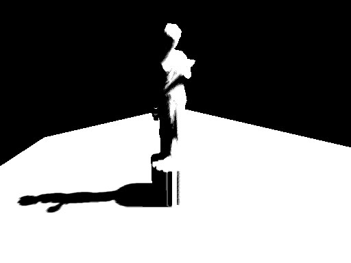
There, the blur maps are ready. To increase the blurriness of the shadows, increase the texel sampling distance. The last step, of course, is to project the blurred map back onto the scene in screen space.
After first Gaussian pass)
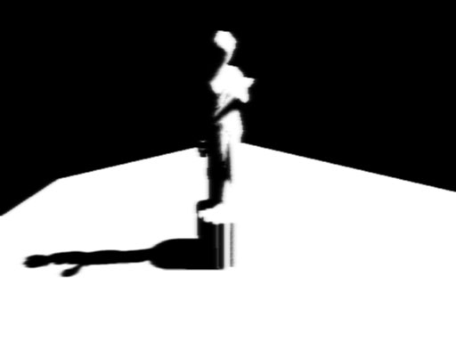
After second Gaussian pass
Step 4: Rendering the shadowed scene
To project the blur map onto the scene, we render the scene as usual, but project the blur map using screen-space coordinates. We use the clip space position with some hard-coded math to generate the screen-space coordinates. The vertex and pixel shaders shown below render the scene with per-pixel lighting along with shadows.
struct VSOUTPUT_SCENE
{
float4 vPosition : POSITION;
float2 vTexCoord : TEXCOORD0;
float4 vProjCoord : TEXCOORD1;
float4 vScreenCoord : TEXCOORD2;
float3 vNormal : TEXCOORD3;
float3 vLightVec : TEXCOORD4;
float3 vEyeVec : TEXCOORD5;
};
VSOUTPUT_SCENE VS_Scene( float4 inPosition : POSITION, float3 inNormal : NORMAL,
float2 inTexCoord : TEXCOORD0 )
{
VSOUTPUT_SCENE OUT = (VSOUTPUT_SCENE)0;
OUT.vPosition = mul( inPosition, g_matWorldViewProj );
OUT.vTexCoord = inTexCoord;
OUT.vProjCoord = mul( inPosition, g_matTexture );
OUT.vScreenCoord.x = ( OUT.vPosition.x * 0.5 + OUT.vPosition.w * 0.5 );
OUT.vScreenCoord.y = ( OUT.vPosition.w * 0.5 - OUT.vPosition.y * 0.5 );
OUT.vScreenCoord.z = OUT.vPosition.w;
OUT.vScreenCoord.w = OUT.vPosition.w;
float4 vWorldPos = mul( inPosition, g_matWorld );
OUT.vNormal = mul( inNormal, g_matWorldIT );
OUT.vLightVec = g_vLightPos.xyz - vWorldPos.xyz;
OUT.vEyeVec = g_vEyePos.xyz - vWorldPos.xyz;
return OUT;
}
We add an additional spot term by projecting down a spot texture from the light. This not only simulates a spot lighting effect, it also cuts out parts of the scene outside the shadow map. The spot map is projected down using standard projective texturing.
float4 PS_Scene( VSOUTPUT_SCENE IN ) : COLOR0
{
IN.vNormal = normalize( IN.vNormal );
IN.vLightVec = normalize( IN.vLightVec );
IN.vEyeVec = normalize( IN.vEyeVec );
float4 vColor = tex2D( ColorSampler, IN.vTexCoord );
float ambient = 0.0f;
float diffuse = max( dot( IN.vNormal, IN.vLightVec ), 0 );
float specular = pow(max(dot( 2 * dot( IN.vNormal, IN.vLightVec ) * IN.vNormal
- IN.vLightVec, IN.vEyeVec ), 0 ), 8 );
if( diffuse == 0 ) specular = 0;
float fShadowTerm = tex2Dproj( BlurVSampler, IN.vScreenCoord );
float fSpotTerm = tex2Dproj( SpotSampler, IN.vProjCoord );
return (ambient * vColor) +
(diffuse * vColor * g_vLightColor * fShadowTerm * fSpotTerm) +
(specular * vColor * g_vLightColor.a * fShadowTerm * fSpotTerm);
}
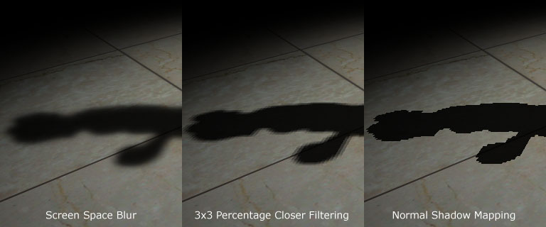
That's it! We have soft edged shadows that look quite nice! The advantage of this technique is that it completely removes edge-aliasing artifacts that the shadow mapping technique suffers from. Another advantage is that one can generate soft shadows for multiple lights with a small memory overhead. When dealing with multiple lights, all you need is one shadow map per light, whereas the screen and blur buffers can be common to all the lights! Finally, this technique can be applied to both shadow maps and shadow volumes, so irrespective of the shadowing technique, you can generate soft-edged shadows with this method. One disadvantage is that this method is a wee bit fill-rate intensive due to the Gaussian filter. This can be minimized by using smaller blur buffers and slightly sacrificing the visual quality.
Here's a comparison between the approach mentioned here, 3x3 percentage closer filtering and normal shadow mapping.
Thank you for reading my article. I hope you liked it. If you have any doubts, questions or comments, please feel free to mail me at anidex@yahoo.com. Here's the source code.
References
- Hardware Shadow Mapping. Cass Everitt, Ashu Rege and Cem Cebenoyan.
- Hardware-accelerated Rendering of Antialiased Shadows with Shadow Maps. Stefan Brabec and Hans-Peter Seidel.
Discuss this article in the forums
Date this article was posted to GameDev.net: 1/18/2005
(Note that this date does not necessarily correspond to the date the article was written)
See Also:
Hardcore Game Programming
Shadows
------------------------------------------------------------------------------------------------------------------------------------------------------
------------------------------------------------------------------------------------------------------------------------------------------------------
介紹
...
1
近況
...
1
軟陰影
...
2
那么它如何工作?
...
2
步驟一:渲染陰影映射圖(
shadow map
)
...
2
步驟二:將帶陰影的場景渲染到緩沖中
...
4
步驟三:對屏幕緩沖進行模糊
...
7
步驟四:渲染帶陰影的場景
...
11
參考文獻
...
13
?
?
最初,動態陰影技術只有在有限的幾種情況下才能實現。但是,隨著強大的可編程圖形硬件的面世,動態陰影技術已經完全取代了以前的如
light map
這樣的靜態陰影技術及像
projected shadows
這樣的半動態陰影技術。目前兩種流行的動態陰影技術分別是
shadow volumes
和
shadow mapping
。
?
shadow volumes
技術是一種基于幾何形體的技術,它需要幾何體在一定方向的燈光下的輪廓去產生一個封閉的容積,然后通過光線的投射就可以決定場景的陰影部分(常常使用模板緩沖去模擬光線的投射)。這項技術是像素精確的,不會產生任何的鋸齒現象,但是與其他的技術一樣,它也有缺點。最主要的兩個問題一是極度依賴幾何形體,二是需要非常高的填充率。由于這些缺點,使得
shadow mapping
技術漸漸地變得更為流行起來。
陰影映射技術是一種圖像空間的技術,它首先在以光源位置作為視點的情況下渲染整個場景的深度信息,然后再使用這些深度信息去決定場景的哪一部分是處于陰影之中。雖然這項技術有許多優點,但它有鋸齒現象并且依賴
z-
緩沖技術。不過它的優點足以抵消它的這些缺點,因此本文選用了這項技術。
?
硬陰影破壞了場景的真實性,因此,我們必須仿造軟陰影來提升場景的可視效果。許多狂熱的學者都拿出了描述軟陰影技術的論文。但實際上,這些技術大部分都是很難在一個較為復雜的場景下實現實時效果。直到我們擁有了能克服這些技術局限性的硬件后,我們才真正的采用了這些方法。
本文采用了基于圖像空間的方法,并利用
shadow mapping
技術來產生軟陰影。這個方法不能產生完美的陰影,因為沒有真正的模擬出本影和半影,但它不僅僅可以解決陰影映射技術的鋸齒現象,還能以賞心悅目的軟陰影來提升場景的可視效果。
?
首先,我們生成陰影映射圖(
shadow map
),具體方法是以光源位置為視點,將場景的深度信息渲染到浮點格式的緩沖中去。然后我們不是像通常那樣在陰影下渲染場景,而是將陰影區域渲染到一幅屏幕大小的緩沖中去,這樣就可以使用
bloom filter
進行模糊并將它投射回屏幕空間中使其顯示在屏幕上。是不是很簡單?
本文只處理了聚光燈源這種情況,但可以很方便的推廣到點光源上。
下面是具體步驟:
通過將深度信息寫入浮點紋理的方法產生陰影映射圖(
shadow map
)。
深度比較后將場景的陰影部分渲染到定點紋理,此時不要任何的燈光。
使用
bloom filter
模糊上一步的紋理,本文采用了
separable Gaussian filter
,
也可用其他的方法。
在所有的光源下將上一步模糊后的紋理投射到屏幕空間中,從而得到最終的效果。
步驟
一
:渲染陰影映射圖(
shadow map
)
首先,我們需要創建一個能保存屏幕深度信息的紋理。因為要把這幅紋理作為
render target
,所以我們還要創建一個表面(
surface
)來保存紋理的表面信息。由于深度信息值的范圍很大因此這幅紋理必須是浮點類型的。
R32F
的格式有足夠的精度可以滿足我們的需要。下面是創建紋理的代碼片斷:
								if

						(

				 FAILED( g_pd3dDevice->CreateTexture( SHADOW_MAP_SIZE,
???????????????????? SHADOW_MAP_SIZE, 1, D3DUSAGE_RENDERTARGET,
???????????????????? D3DFMT_R32F, D3DPOOL_DEFAULT, &g_pShadowMap,
						????????????????????
						NULL ) ) )
{
						??
						MessageBox( g_hWnd, "Unable to create shadow map!",
?????????????? "Error", MB_OK | MB_ICONERROR );
						??

								return
						 E_FAIL;
}
?
g_pShadowMap->GetSurfaceLevel( 0, &g_pShadowSurf );
?
為了完成陰影映射圖,我們要把場景的深度信息渲染到陰影映射圖中。為此在光源的世界
-
視點
-
投影變換矩陣(
world-view-projection matrix
)下渲染整個場景。下面是構造這些矩陣的代碼:
						D3DXMatrixLookAtLH(

				 &matView, &vLightPos, &vLightAim, &g_vUp );
						D3DXMatrixPerspectiveFovLH(

				 &matProj, D3DXToRadian(30.0f),
						1.0f

				, 1.0f, 1024.0f );
//
實際上作者在例程中使用的是
D3DXMatrixOrthoLH( &matProj, 45.0f, 45.0f, 1.0f, //1024.0f )
。這個函數所構造的
project
矩陣與
D3DXMatrixPerspectiveFovLH
()構造的
//
不同之處在于:它沒有透視效果。即物體的大小與視點和物體的距離沒有關系。顯然例
//
程中模擬的是平行光源(
direction light
),而這里模擬的是聚光燈源(
spot light
不知翻譯得對不對?)
						matLightViewProj

				 = matWorld * matView * matProj;
?
下面是渲染場景深度的頂點渲染和像素渲染的代碼:
?
								struct


				 VSOUTPUT_SHADOW
{
						??

								float4
						 vPosition??? : POSITION;
						??

								float
								? fDepth
						?????? : TEXCOORD0;
};
?
VSOUTPUT_SHADOW VS_Shadow(float4 inPosition : POSITION )
{
??
?? VSOUTPUT_SHADOW OUT = (VSOUTPUT_SHADOW)0;
??
?? OUT.vPosition = mul( inPosition, g_matLightViewProj );
??
?? OUT.fDepth = OUT.vPosition.z;
						??

								return
						 OUT;
}
這里我們將頂點的位置與變換矩陣相乘,并將變換后的
z
值作為深度。在像素渲染中將深度值以顏色(
color
)的方式輸出。
								float4


								? PS

				_Shadow( VSOUTPUT_SHADOW IN ) : COLOR0
{
??
						??

								return

						 float4( IN.fDepth, IN.fDepth, IN.fDepth, 1.0f );
}
瞧,我們完成了陰影映射圖,下面就是以顏色方式輸出的陰影映射圖,深藍色部分表明較小的深度值,淺藍色部分表明較大的深度值。
下面,我們要把場景的帶陰影的部分渲染到并不立即顯示的緩沖中,使我們可以進行模糊處理,然后再將它投射回屏幕。首先把場景的陰影部分渲染到一幅屏幕大小的定點紋理中。
								if

						(

				 FAILED( g_pd3dDevice->CreateTexture( SCREEN_WIDTH,
??????????? SCREEN_HEIGHT, 1, D3DUSAGE_RENDERTARGET,
						?????
						??????D3DFMT_A8R8G8B8, D3DPOOL_DEFAULT,
??????????? &g_pScreenMap, NULL ) ) )
{
						??
						MessageBox( g_hWnd, "Unable to create screen map!",
?????????????? "Error", MB_OK | MB_ICONERROR );
						??

								return
						 E_FAIL;
}
g_pScreenMap->GetSurfaceLevel( 0, & g_pScreenSurf );
為了獲得投影紋理坐標(
projective texture coordinates
),我們需要一個紋理矩陣,作用是把投影空間(
projection space
)中的位置變換到紋理空間(
texture space
)中去。
								float


				 fTexOffs = 0.5 + (0.5 / (float)SHADOW_MAP_SIZE);
D3DXMATRIX matTexAdj(0.5f,???? 0.0f,???? ?0.0f, ?0.0f,
						???
						??????????????????
						????
						0.0f,???? -0.5f,?? ??0.0f, ?0.0f,
						?????????????????????
						????
						0.0f,??? ??0.0f,???? 1.0f, ?0.0f,
						?????????????????????
						????
						fTexOffs, fTexOffs, 0.0f, 1.0f );
				//
				這個矩陣是把
				projection space
				中范圍為
				[-1
				,
				1]
				的
				x,y
				坐標值轉換到紋理空間中
				//[0
				,
				1]
				的范圍中去。注意
				y
				軸的方向改變了。那個
				(0.5 / (float)SHADOW_MAP_SIZE)
				//
				的值有什么作用我還不清楚,原文也沒有說明。
?
						matTexture

				 = matLightViewProj * matTexAdj;
?
我們像往常那樣通過深度的比較來獲得陰影因數,但隨后并不是像平常那樣輸出整個照亮了的場景,我們只輸出陰影因數。下面的頂點渲染和像素渲染完成這個工作。
								struct


				 VSOUTPUT_UNLIT
{
						??

								float4
						 vPosition?? : POSITION;
						??

								float4
						 vTexCoord?? : TEXCOORD0;
						??

								float
								? fDepth
						????? : TEXCOORD1;
};
?
VSOUTPUT_UNLIT VS_Unlit(float4 inPosition : POSITION )
{
??
?? VSOUTPUT_UNLIT OUT = (VSOUTPUT_UNLIT)0;
?
??
?? OUT.vPosition = mul( inPosition, g_matWorldViewProj );
?
??
?? OUT.vTexCoord = mul( inPosition, g_matTexture );
?
??
?? OUT.fDepth = mul( inPosition, g_matLightViewProj ).z;
?
						??

								return
						 OUT;
}
我們采用
percentage closer filtering (PCF)
來平滑鋸齒邊緣。為了完成“
PCF
”,我們簡單的對周圍
8
個紋理點進行采樣,并取得它們深度比較的平均值。
tex2Dproj
()函數以及轉換到紋理空間的向量(x,y,z,w)對紋理進//行采樣。這與d3d9sdk中shadowmap例子用tex2D()及向量(x,y)進行采樣不同。具體//區別及原因很容易從程序中看出,我就不再啰嗦了。
								float4


								? PS

				_Unlit( VSOUTPUT_UNLIT IN ) : COLOR0
{
??
						??

								float4
						 vTexCoords[9];
??
						??

								float
						 fTexelSize = 1.0f / 1024.0f;
?
??
						??
						VTexCoords[0] = IN.vTexCoord;
						??
						vTexCoords[1] = IN.vTexCoord + float4( -fTexelSize, 0.0f, 0.0f, 0.0f );
						??
						vTexCoords[2] = IN.vTexCoord + float4(? fTexelSize, 0.0f, 0.0f, 0.0f );
						??
						vTexCoords[3] = IN.vTexCoord + float4( 0.0f, -fTexelSize, 0.0f, 0.0f );
						??
						vTexCoords[6] = IN.vTexCoord + float4( 0.0f,? fTexelSize, 0.0f, 0.0f );
						??
						vTexCoords[4] = IN.vTexCoord + float4( -fTexelSize, -fTexelSize, 0.0f, 0.0f );
						??
						vTexCoords[5] = IN.vTexCoord + float4(? fTexelSize, -fTexelSize, 0.0f, 0.0f );
						??
						vTexCoords[7] = IN.vTexCoord + float4( -fTexelSize,? fTexelSize, 0.0f, 0.0f );
						??
						vTexCoords[8] = IN.vTexCoord + float4(? fTexelSize,? fTexelSize, 0.0f, 0.0f );
??
						??

								float
						 fShadowTerms[9];
						??

								float
						 fShadowTerm = 0.0f;
						??

								for(
						int i = 0; i < 9; i++ )
?? {
						?????

								float
						 A = tex2Dproj( ShadowSampler, vTexCoords[i] ).r;
						?????

								float
						 B = (IN.fDepth - 0.1f);
?
?????
						?????
						fShadowTerms[i] = A < B ? 0.0f :1.0f;
						?????
						fShadowTerm
						???? += fShadowTerms[i];
?? }
??
						??
						fShadowTerm /= 9.0f;
						??

								return
						 fShadowTerm;
}
屏幕緩沖完成了,我們還需要進行模糊工作。
我們采用
seperable gaussian filter
模糊屏幕緩沖。但我們也可以用
Poisson filter
。這次的
render targets
是
A8R8G8B8
的紋理和相關的表面。我們需要兩個
render targets
,一個進行水平階段,一個進行垂直階段。
								for

						(


						int i = 0; i < 2; i++ )
{
						??

								if( FAILED( g_pd3dDevice->CreateTexture( SCREEN_WIDTH,
?????????????????????????? SCREEN_HEIGHT, 1, D3DUSAGE_RENDERTARGET,
?????????????????????????? D3DFMT_A8R8G8B8, D3DPOOL_DEFAULT,
?????????????????????????? &g_pBlurMap[i], NULL ) ) )
?? {
						?????
						MessageBox( g_hWnd, "Unable to create blur map!",
????????????????? "Error", MB_OK | MB_ICONERROR );
						?????

								return
						 E_FAIL;
?? }
?
?? g_pBlurMap[i]->GetSurfaceLevel( 0, & g_pBlurSurf[i] );
}
我們用下面的代碼生成
15
個高斯偏移量(
Gaussian offsets
)及他們的權重(
corresponding weights
)。
								float


				 GetGaussianDistribution( float x, float y, float rho )
{
						??

								float
						 g = 1.0f / sqrt( 2.0f * 3.141592654f * rho * rho );
						??

								return
						 g * exp( -(x * x + y * y) / (2 * rho * rho) );
}
?
								void


				 GetGaussianOffsets( bool bHorizontal,
???????????????????????? D3DXVECTOR2 vViewportTexelSize,
???????????????????????? D3DXVECTOR2* vSampleOffsets,
						????????????????????????

								float
						* fSampleWeights )
{
??
						??
						fSampleWeights[0] = 1.0f * GetGaussianDistribution( 0, 0, 2.0f );
						??
						vSampleOffsets[0] = D3DXVECTOR2( 0.0f, 0.0f );
??
						??

								if( bHorizontal )
?? {
						?????

								for(
						int i = 1; i < 15; i += 2 )
????? {
						????????
						vSampleOffsets[i + 0] = D3DXVECTOR2( i * vViewportTexelSize.x, 0.0f );
						????????
						vSampleOffsets[i + 1] = D3DXVECTOR2( -i * vViewportTexelSize.x, 0.0f );
						????????
						fSampleWeights[i + 0] = 2.0f * GetGaussianDistribution( float(i + 0), 0.0f, 3.0f );
						????????
						fSampleWeights[i + 1] = 2.0f * GetGaussianDistribution( float(i + 1), 0.0f, 3.0f );
????? }
?? }
						??

								else
???{
						?????

								for(
						int i = 1; i < 15; i += 2 )
????? {
						????????
						vSampleOffsets[i + 0] = D3DXVECTOR2( 0.0f, i * vViewportTexelSize.y );
						????????
						vSampleOffsets[i + 1] = D3DXVECTOR2( 0.0f, -i * vViewportTexelSize.y );
						????????
						fSampleWeights[i + 0] = 2.0f * GetGaussianDistribution( 0.0f, float(i + 0), 3.0f );
						????????
						fSampleWeights[i + 1] = 2.0f * GetGaussianDistribution( 0.0f, float(i + 1), 3.0f );
????? }
?? }
}
為了模糊屏幕緩沖,我們將模糊映射圖(
blur map
)作為
render target
,使用下面的頂點渲染和像素渲染代碼渲染一個與屏幕等大的方塊。
//
作者在程序中預先定義的屏幕大小是1024 * 768,而隨后定義的與屏幕等大的方塊為:
//
pVertices[0].p = D3DXVECTOR4( 0.0f, 0.0f, 0.0f, 1.0f );
//? pVertices[1].p = D3DXVECTOR4( 0.0f, 768 / 2, 0.0f, 1.0f );
//? pVertices[2].p = D3DXVECTOR4( 1024 / 2, 0.0f, 0.0f, 1.0f );
//? pVertices[3].p = D3DXVECTOR4( 1024 / 2, 768 / 2, 0.0f, 1.0f );
//?
這種方法與d3dsdk中HDRLight中獲得render target
的
width and height
然后再構造的
//?
方法不同
:
// svQuad[0].p = D3DXVECTOR4(-0.5f, -0.5f, 0.5f, 1.0f);
// svQuad[1].p = D3DXVECTOR4(Width-0.5f, -0.5f, 0.5f, 1.0f);
// svQuad[2].p = D3DXVECTOR4(-0.5f, Height-0.5f, 0.5f, 1.0f);
// svQuad[3].p = D3DXVECTOR4(Width-0.5f,fHeight-0.5f, 0.5f, 1.0f);
//
而一般定義的窗口大小往往與從render target獲得的width and height不相同。
//
而二者的fvf都是D3DFVF_XYZRHW。這兩種方法有什么區別我一直沒想通。
?
								struct


				 VSOUTPUT_BLUR
{
						??

								float4
						 vPosition??? : POSITION;
						??

								float2
						 vTexCoord??? : TEXCOORD0;
};
?
VSOUTPUT_BLUR VS_Blur(float4 inPosition : POSITION, float2 inTexCoord : TEXCOORD0 )
{
??
?? VSOUTPUT_BLUR OUT = (VSOUTPUT_BLUR)0;
??
?? OUT.vPosition = inPosition;
??
?? OUT.vTexCoord = inTexCoord;
						??

								return
						 OUT;
}
						float4

				PS_BlurH( VSOUTPUT_BLUR IN ): COLOR0
{
??
						??

								float4
						 vAccum = float4( 0.0f, 0.0f, 0.0f, 0.0f );
??
						??

								for(
						int i = 0; i < 15; i++ )
?? {
						?????
						vAccum += tex2D( ScreenSampler, IN.vTexCoord + g_vSampleOffsets[i] ) * g_fSampleWeights[i];
?? }
						??

								return
						 vAccum;
}
?
						float4

				 PS_BlurV( VSOUTPUT_BLUR IN ): COLOR0
{
??
						??

								float4
						 vAccum = float4( 0.0f, 0.0f, 0.0f, 0.0f );
??
						??

								for(
						int i = 0; i < 15; i++ )
?? {
						?????
						vAccum += tex2D( BlurHSampler, IN.vTexCoord + g_vSampleOffsets[i] ) * g_fSampleWeights[i];
?? }
						??

								return
						 vAccum;
}
這里,模糊映射圖已經完成了,為了增加陰影的模糊程度,增加了紋理上點的采樣距離。最后一步自然是將模糊后的紋理圖投射回屏幕空間使其顯示在屏幕上。
After first Gaussian pass
After second Gaussian pass
為了將模糊后的紋理投射到屏幕上,我們像平常那樣渲染場景,但投影模糊后的紋理時要使用屏幕空間的坐標。我們使用裁剪空間的坐標和一些數學方法來產生屏幕空間的坐標。下面的頂點渲染和像素渲染將完成這個工作:
								struct


				 VSOUTPUT_SCENE
{
						??

								float4
						 vPosition????? : POSITION;
						??

								float2
						 vTexCoord????? : TEXCOORD0;
						??

								float4
						 vProjCoord???? : TEXCOORD1;
						??

								float4
						 vScreenCoord?? : TEXCOORD2;
						??

								float3
						 vNormal??????? : TEXCOORD3;
						??

								float3
						 vLightVec????? : TEXCOORD4;
						??

								float3
						 vEyeVec??????? : TEXCOORD5;
};
VSOUTPUT_SCENE VS_Scene(float4 inPosition : POSITION,
						????????????????????????

								float3
						 inNormal : NORMAL,
						????????????????????????

								float2
						 inTexCoord : TEXCOORD0 )
{
?? VSOUTPUT_SCENE OUT = (VSOUTPUT_SCENE)0;
??
?? OUT.vPosition = mul( inPosition, g_matWorldViewProj );
?
??
?? OUT.vTexCoord = inTexCoord;
?
??
?? OUT.vProjCoord = mul( inPosition, g_matTexture );
?
??
裁剪空間的坐標轉換到屏幕空間的坐標,方法和
裁剪空間的坐標轉換
				//?
				紋理空間的坐標的方法很相似。
?? OUT.vScreenCoord.x = ( OUT.vPosition.x * 0.5 + OUT.vPosition.w * 0.5 );
?? OUT.vScreenCoord.y = ( OUT.vPosition.w * 0.5 - OUT.vPosition.y * 0.5 );
?? OUT.vScreenCoord.z = OUT.vPosition.w;
?? OUT.vScreenCoord.w = OUT.vPosition.w;
?
??
						??
						float4 vWorldPos = mul( inPosition, g_matWorld );
?
??
?? OUT.vNormal = mul( inNormal, g_matWorldIT );
?
??
?? OUT.vLightVec = g_vLightPos.xyz - vWorldPos.xyz;
?
??
?? OUT.vEyeVec = g_vEyePos.xyz - vWorldPos.xyz;
						??

								return
						 OUT;
}
						float4

				 PS_Scene( VSOUTPUT_SCENE IN ) : COLOR0
{
??
?? IN.vNormal?? = normalize( IN.vNormal );
?? IN.vLightVec = normalize( IN.vLightVec );
?? IN.vEyeVec?? = normalize( IN.vEyeVec );
??
						??

								float4
						 vColor? = tex2D( ColorSampler, IN.vTexCoord );
??
						??

								float
						 ambient? = 0.0f;
						??

								float
						 diffuse? = max( dot( IN.vNormal, IN.vLightVec ), 0 );
						??

								float
						 specular = pow(max(dot( 2 * dot( IN.vNormal, IN.vLightVec ) * IN.vNormal
???????????????????????????????? - IN.vLightVec, IN.vEyeVec ), 0 ), 8 );
						??

								if( diffuse == 0 ) specular = 0;
??
						??

								float
						 fShadowTerm = tex2Dproj( BlurVSampler, IN.vScreenCoord );
??
						??

								float
						 fSpotTerm = tex2Dproj( SpotSampler, IN.vProjCoord );
??
						??

								return
						 (ambient * vColor) +
????????? (diffuse * vColor * g_vLightColor * fShadowTerm * fSpotTerm) +
????????? (specular * vColor * g_vLightColor.a * fShadowTerm * fSpotTerm);
}
終于完成了。看上去不錯。該技術的優點一是解決了鋸齒問題,二是在多光源,低內存下實現了軟陰影。另外該技術與陰影生成方法無關,可以很容易的在
shadow volumes
技術中采用這項技術。缺點是由于進行了模糊處理而需要一些填充率。
下面是不同階段的效果比較圖: